Step 1
|
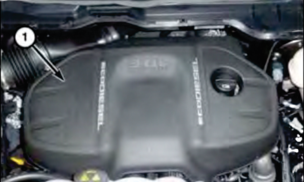
Remove the injector cover by firmly pulling on
each side of the cover to dislodge the locating
pins and free the cover from the engine.
|
 |
Step 2
|
Remove the sound absorbing foam pads that
are under the injection cover to expose EGR
tube (in the white heat wrap)
|
 |
Step 3
|
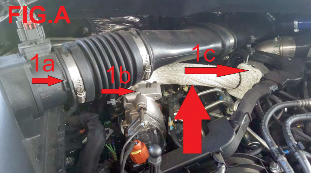
Loosen the clamp on the flexible rubber hose on the air intake tube at the filter side. See
1a in
Fig. A Once the clamp is loose, pull the hose out and away from the filter box. Lift up carefully along the intake tube until you release the ball and socket style joint holding the intake tube in place. With this joint loose you will have enough room to lift the intake tube up enough to easily access the bolts on the EGR tube.
|
Step 4
|
Using a socket, remove the two 10mm bolts holding the EGR tube on the cooler side. See
1b in
Fig. A Keep these bolts!
|
Step 5
|
Using a socket, remove the two 8mm bolts holding the EGR tube on the intake manifold side. See
1c in
Fig. A |
Step 6
|
With all 4 bolts removed lift up on the EGR tube from the cooler side until it clears and then slide the EGR tube to the passenger side to remove it from the intake manifold.
|
Step 7
|
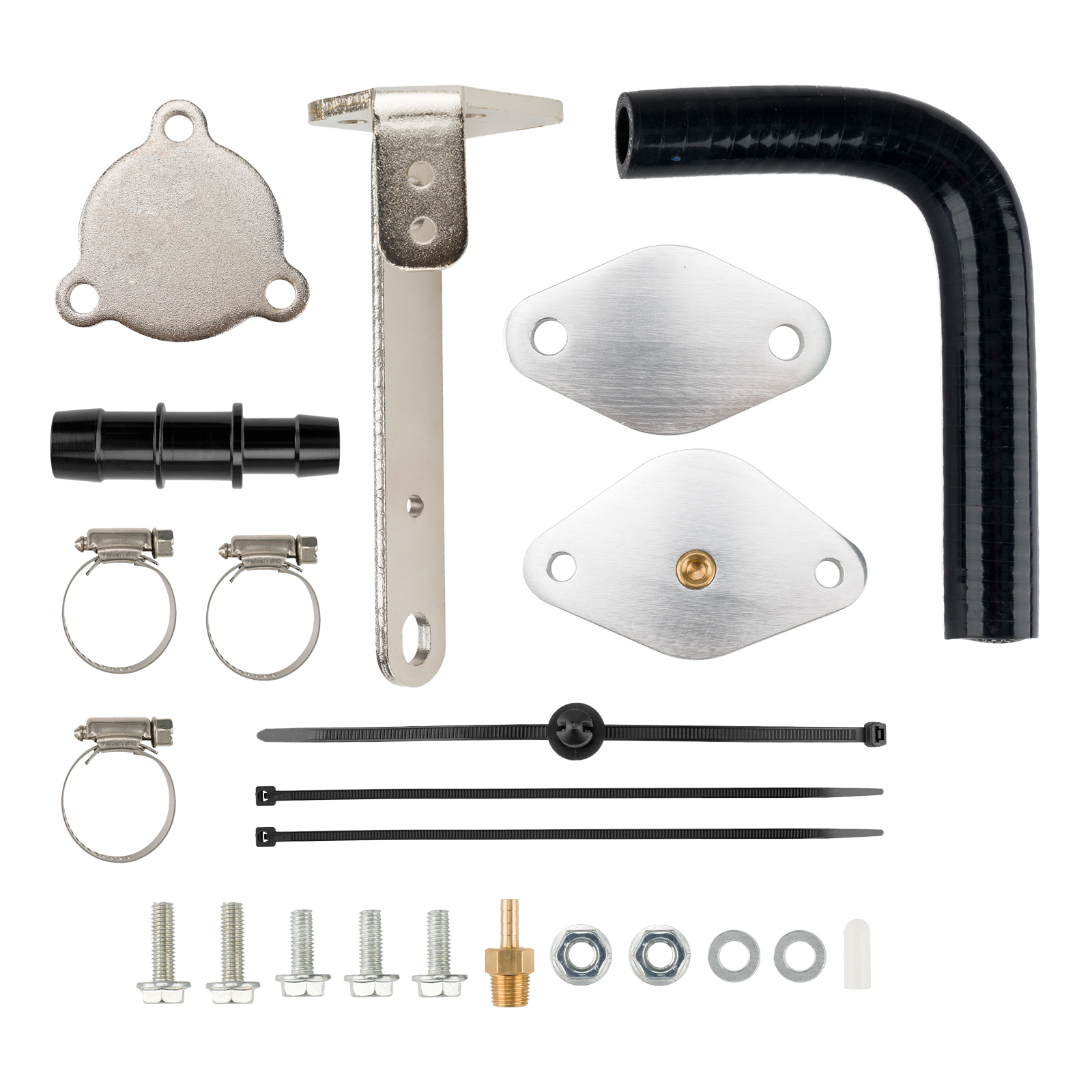
Using the provided 2 x 10mm bolts, install blocker plate Part onto the valve cover port.
|
Note:
|
The intake side blocker plate comeswith a port for mounting an optional boost gauge. If using an additional boost gauge install. If no boost gauge is desired then leave plug in place.
|
If you are doing a phase 2 install, then skip ahead to step 11. If you are doing a phase 1 install only then continue with steps 8-10 only.
|
Step 8
|
Remove the gasket from the EGR tube on the cooler side by gently pushing on the tabs that go along the sides. Reinstall this gasket onto your cooler side blocker plate. Using the factory 10mm bolts, install your blocker plate.
|
Step 9
|
Reposition the intake tube and reconnect the ball and socket joint. Reinstall intake tube to the filter box and secure clamp.
|
Step 10
|
Reinstall the sound foam and plastic engine cover.
|
At this point your phase 1 install is complete! To continue with phase 2 skip to step 11.
|
Step 11
|
Removing the air filter, box and intake tube
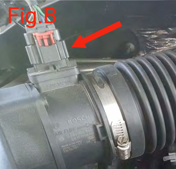
Disconnect the MAF sensor by pulling the red tab out of the connector see
Fig.B Remove intake tube from air box. See step 3
Open the 4 clips that hold the lid onto the air box and remove the lid and filter.
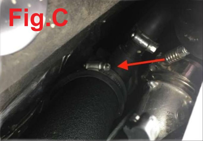
Follow the intake tube, removing it from the ball and socket connection as in step 3. Then locate the clamp holding the intake tube to the turbo
Fig.C. Undo the clamp and remove intake from turbo and out of the way.
Locate 2 plastic pins holding a wiring harness between the filter box and the firewall and remove the two pins to free the box of any wires.
Remove inner wheel well plastic
Now that your filter box should be free from all connection points, lift straight up off of the locating pins and remove from vehicle.
|
 |
 |
Step 12
|
Removing EGR vacuum line
|
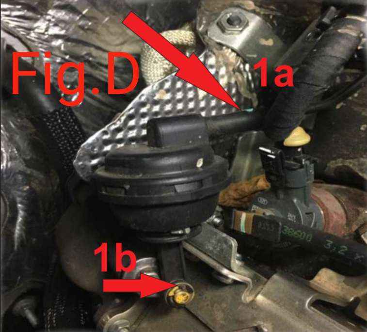
Disconnect the vacuum line from the EGR actuator. See
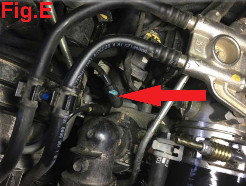
1a in Fig.D Follow the vacuum line from the EGR actuator to the solenoid, removing any clips you find along the way. The solenoid is located on the passenger side of the throttle plate assembly. See
Fig.E Remove the Vacuum line from the solenoid and cap the end with the cap provided in the kit
Carefully guide the vacuum line out towards the front of the truck to remove it completely.
|
 |
 |
Step 13
|
Removing EGR actuator
|
Remove the E-Clip and washer from the EGR actuator. See 1b on Fig.D. DO NOT DROP THE WASHER!!
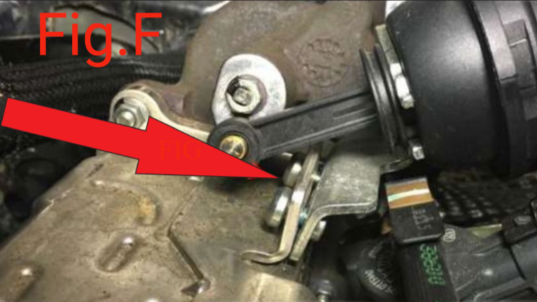
After removing the 2 T-25 bolts from the bracket, pull the actuator off towards the front of the vehicle. See Fig.F
|
 |
Step 14
|
Removing electrical componants
|
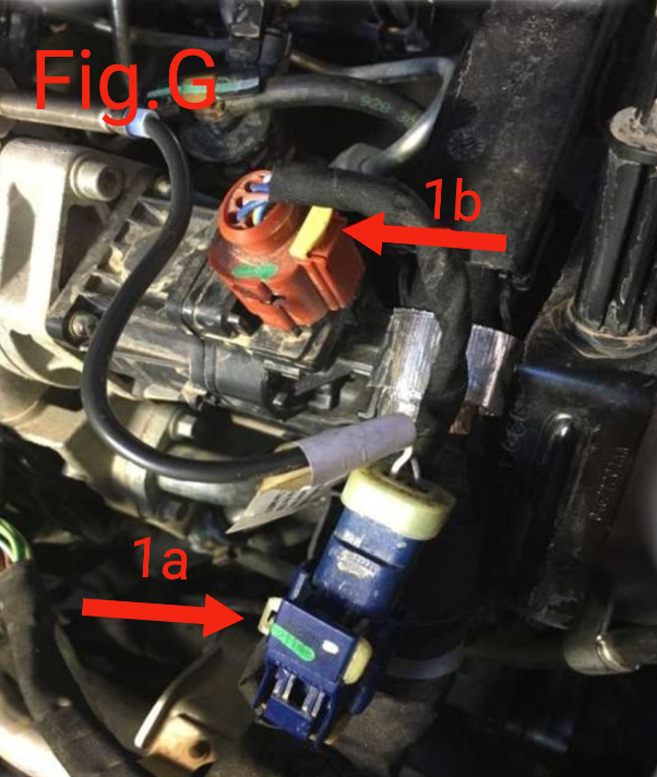
Disconnect the blue connector. See 1a in Fig.G Disconnect the red connector. See
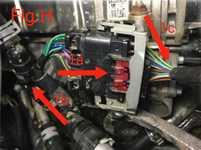
1b in Fig.G Disconnect the large black connector by carefully pulling the red tabs and then lifting the grey handle separating the plug. See
1a in Fig. H With the plug loose, push the fixed part of the plug towards the ground exposing the 2 clips that hold the plug onto the bracket. Remove the plug and any other clips from the bracket.
|
 |
 |
Step 15
|
Coolant lines
|
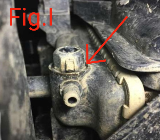
Open your coolant reservoir cap and then locate the radiator drain plug under the front drivers side. You can use a 16mm wrench to open the drain but be very careful not to break the plastic plug itself. see
Fig.I Drain about 1 gallon of coolant or until it begins to drip slowly. Re-tighten and secure the plug.
Locate the two 10mm bolts that hold the rear coolant hose on the body of the EGR. See
1b in Fig.H Start by using pliers to grab the clip holding the top side hose and slide the clip back to free the hose from the coupler. Remove the (2) bolts.
Note: some coolant will drain from the hose and EGR. Locate the front coolant line. See
1c in Fig.H Remove the 28mm bolts.
Do NOT loose the gasket as it will be reused.
|
 |
Step 16
|
Locate the EGR up pipe directly behind the EGR actuator removed in
step #13, Fig.F and remove the 2x10mm bolts that connect the tube to the EGR unit.
|
Step 17
|
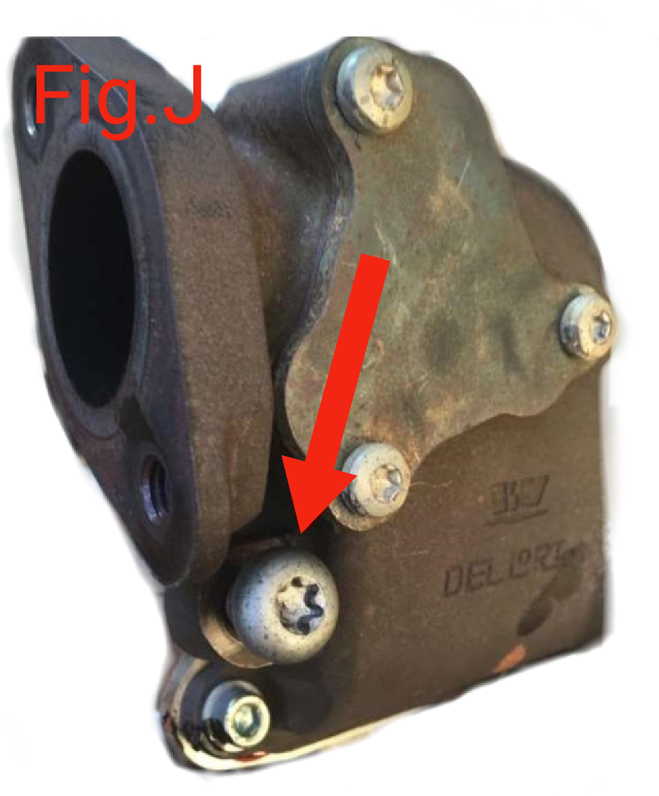
Locate and remove the T-40 Torx bolt just under the flange bolts you took out of the EGR up pipe in the previous step. See
Fig.J
Note: This bolt can be tough to get.
|
 |
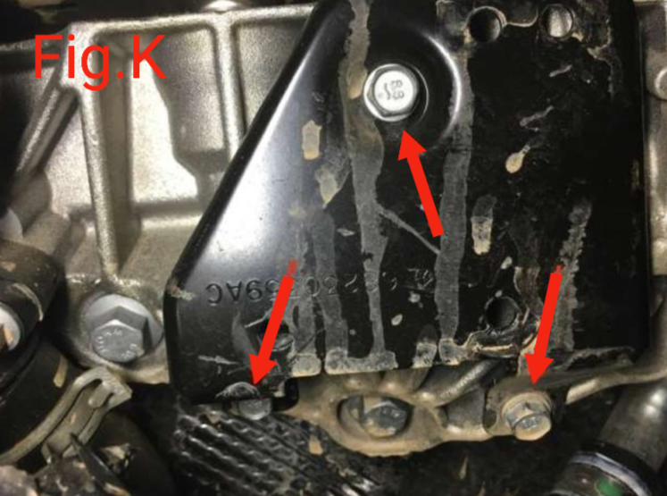
Step 18
|
Locate and remove the 3x13mm bolts from the black, lower support bracket. See
Fig.K |
 |
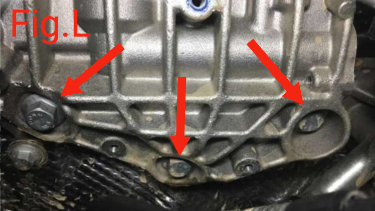
Step 19
|
Remove the (3) 13mm bolts holding the lower EGR cooler manifold in place. The right and left bolts will be reused to bolt on bracket later. See
Fig.L You should now be able to remove the unit from the truck.
|
 |
Step 20
|
Going back to the lower side coolant hose that you left attached to the coupler of
step #15. Again using pliers loosen the clamp holding the rubber hose to the hard coolant line and slide clamp so that the rubber hose can be removed completely. This hose will be replaced with the provided hose
|
Step 21
|
Go back to the EGR up pipe from
step #16 and trace it down to the turbo manifold. Locate and remove the (3) 8mm bolts holding the lower flange in place.
Note: These bolts will be replaced with the provided
Note: This gasket will be reused.
|
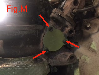
Step 22
|
Using the supplied bolts part #I, and the factory gasket, install the turbo manifold plate, See
Fig.M |
 |
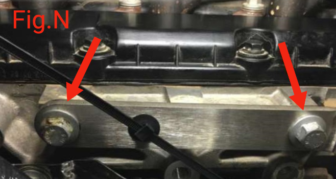
Step 23
|
Using (2) 13 mm bolts from the turbo manifold in
step #19, mount the supplied blocker/mounting plate, using the same holes the bolts came out of. See
Fig.N |
 |
Step 24
|
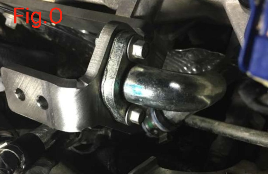
Reusing the (2) 8mm bolts and the included (2) 10mm nuts and washers, fasten the Front Coolant line(
see 1c from Fig.H in step #14) to the block off bracket from
step #23. see
Fig.O Note: Do not forget to use the factory gasket!!
|
 |
Step 25
|
Go back to where you removed the lower coolant line in
step #15 from the hard line and using one of the provided hose clamps, fasten the supplied hose to the hard line.
|
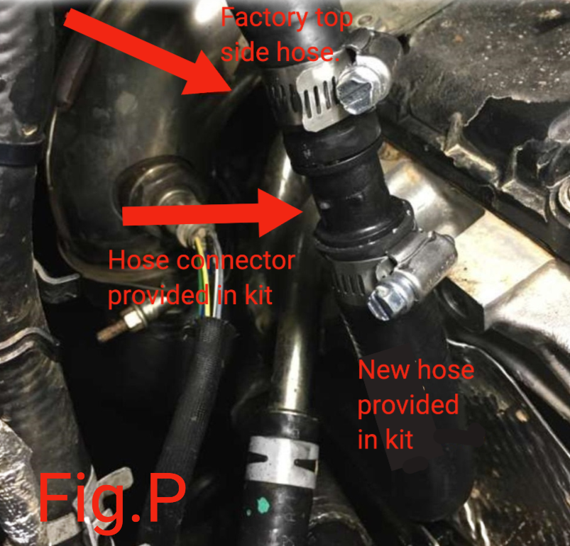
Step 26
|
Now locate the upper coolant line and put one of the supplied hose clamps on the end. Then using, connect the upper and lower lines and secure clamps. see
Fig.P |
 |
Step 27
|
Secure the coolant hose to the new bracket from
step #23 with provided zip tie
|
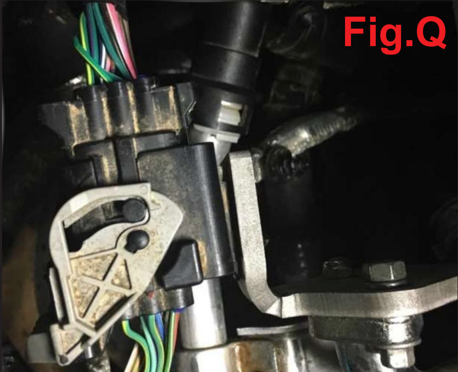
Step 28
|
Reattach the large electrical connector to the new bracket. Tie any left over wiring to the bracket to ensure it cannot be damaged. See
Fig.Q |
 |
Step 29
|
Double check that all bolts, clamps and fittings are tight and secure.
|
Step 30
|
Working backwards, re-install your air filter box, intake tube, sound foam and plastic engine cover.
|
Step 31
|
Start your engine and check for coolant leaks.
|
Note:
|
It is recommended that after bringing your engine up to optimal operating temperatures and running it for a while, double check for any coolant leaks
|