Contents
- I. Introduction & Compliance Notice
- II. Pre-Installation Preparation & Safety Standards
- III. Core Component Analysis of the SunCent 6.0 Powerstroke EGR Delete Kit
- Step-by-Step Installation 6.0 Powerstroke EGR Delete Kit
- V. Critical Installation Pitfalls and Best Practices
- VI. Post-Installation Diagnostic Trouble Codes (DTCs) and Solutions
- FAQs
I. Introduction & Compliance Notice
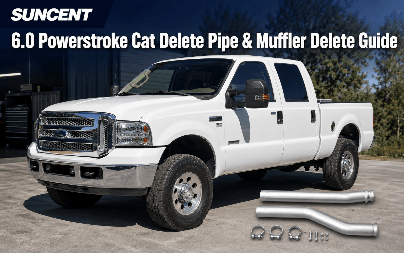
For the 2003–2007 Ford 6.0L Powerstroke diesel engine, the factory EGR cooler and its associated cooling lines are recognized as common system vulnerabilities. This guide provides technical instructions to assist experienced technicians or vehicle owners in installing the SunCent 6.0 Powerstroke EGR Delete Kit. The following sections cover core component analysis, system disassembly, Coolant Bypass establishment, and post-installation validation.
This kit is an emissions system modification component that alters the vehicle's factory emissions logic. This product is intended strictly for legal off-road competition or racing use. Before installation, users must verify local and federal regulatory requirements to avoid legal liabilities resulting from violations of annual inspections, warranties, or legal statutes.
For more instruction guides, click here.
II. Pre-Installation Preparation & Safety Standards
Before beginning work, ensure the vehicle is completely cooled down and all necessary tools and consumables are prepared to navigate the compact and complex engine bay of the 6.0L Powerstroke.
2.1 Confirm Fitment & Configuration
- Compatibility Range: 2003–2007 Ford F250/F350/F450/F550 equipped with the 6.0L V8 Diesel Engine.
- Kit Version: Verify if the kit includes an Up-Pipe. Kits with an Up-Pipe require modification of the exhaust-side branch; kits without an Up-Pipe retain the factory component and focus solely on coolant bypass and blocking.
2.2 Tool & Consumable Checklist
| Category | Required Items |
|---|---|
| Core Tools | Ratchet and socket set (including extensions), torque wrench, hose clamp pliers, small pry bar, and a coolant drain pan. |
| Key Consumables | WD-40 (penetrating lubricant), specialized O-ring grease, high-quality silicone hose zip ties, clean rags, and new coolant mixed to factory specifications. |
2.3 Core Safety Recommendations
- Electrical Safety: You must disconnect the batteries (both negative terminals) to prevent short circuits when removing the alternator or wiring harnesses.
- Contamination Prevention: After removing intake or oil lines, immediately cover openings with sealing tape or clean plugs to prevent debris from entering the engine interior.
- Detailed Documentation: It is strongly recommended to take photos of the wiring harness routing, hose brackets, and clamp orientations before disassembly to ensure precise alignment during reassembly.
2.4 Key Model Year Differences
While 2003–2007 models share the 6.0L platform, strategies must be adjusted for subtle structural differences:
- Hardware Structure (2003–2004): Early versions of the Turbo Pedestal differ from later models; verify alignment angles when removing turbo mounting bolts.
- Peripheral Attachments: Variations exist in wire harness routing, sensor connector types, and fan shroud mounting; rely on pre-disassembly photos for reassembly.
- Software Logic (2005–2007): Later models feature more sensitive EGR flow monitoring. Installing a Delete Kit on these years frequently triggers EGR-related Diagnostic Trouble Codes (DTCs), typically requiring aftermarket tuning to clear lights and optimize engine logic.
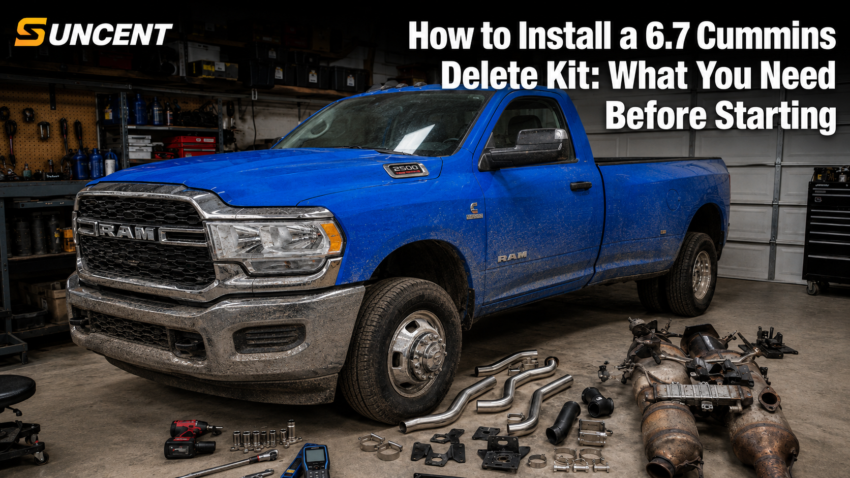
III. Core Component Analysis of the SunCent 6.0 Powerstroke EGR Delete Kit
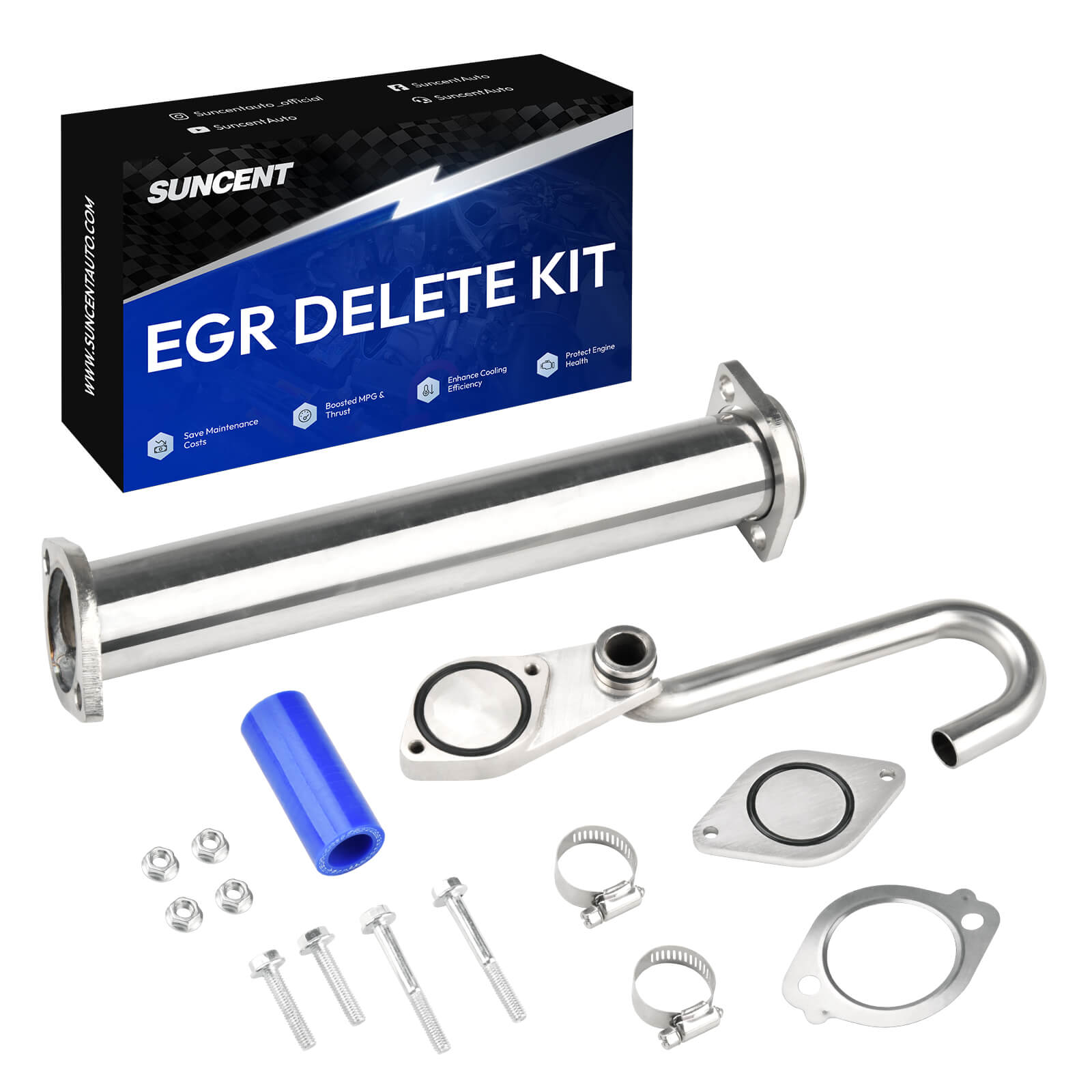
Before beginning construction, please verify the completeness of the kit against the following list and ensure you understand the role of each component in the cooling and exhaust paths:
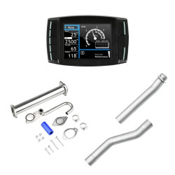
3.1 Coolant Bypass Components
- 180-Degree Stainless Steel Coolant Tube: A "J-shaped" stainless steel pipe responsible for rerouting coolant flow to bypass the removed EGR Cooler.
- Silicone Hose & Clamps: A blue silicone hose serves as a flexible connector. Used with two stainless steel worm gear clamps, it secures the tube to the oil cooler nipple to prevent coolant leaks.
3.2 Sealing Components
- EGR Cooler Adapter (Billet Adapter): An aluminum adapter featuring a pre-installed O-ring. It connects the stainless steel tube to the intake manifold and serves as a critical defense against coolant entering the intake tract.
- EGR Valve Closing Plate: A diamond-shaped cover plate. After removing the factory EGR valve, it is used with a specialized gasket to seal the opening at the top of the intake manifold.
3.3 Exhaust Side and Fasteners
- Delete Up-Pipe: A straight-through stainless steel exhaust pipe used to replace the factory branched pipe. It connects to the turbo and exhaust manifold using the included metal gaskets.
- Mounting Hardware: The kit includes 4 flange nuts and 3 mounting bolts of varying lengths. It is vital to distinguish bolt lengths during installation to ensure even clamping pressure on the Billet Adapter and closing plate.

Step-by-Step Installation 6.0 Powerstroke EGR Delete Kit
System Disassembly
The core objective of this phase is to clear the space above the engine to create a clear line of sight for removing the factory EGR Cooler and Up-Pipe. Because the 6.0L engine bay is extremely cramped, anti-contamination procedures must be strictly enforced during disassembly.
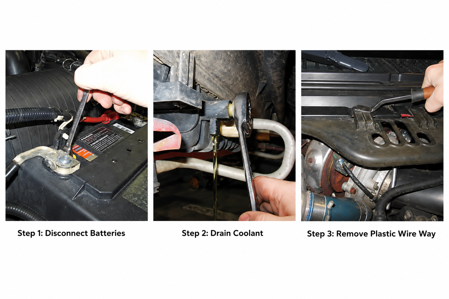
4.1 Phase One: Power Disconnection, Pressure Relief, and Accessory Removal
- Disconnect Batteries: Completely remove the negative battery terminals to ensure no short circuits occur when moving the alternator or wiring harness later.
- Drain Coolant: Once the engine is completely cooled, drain the coolant through the radiator drain valve into a clean container to avoid environmental pollution or fluid infiltration into precision sensors.
- Move Wiring Harness Bracket: Loosen the plastic wiring harness tray above the turbo and secure it toward the windshield to clear the top work surface.
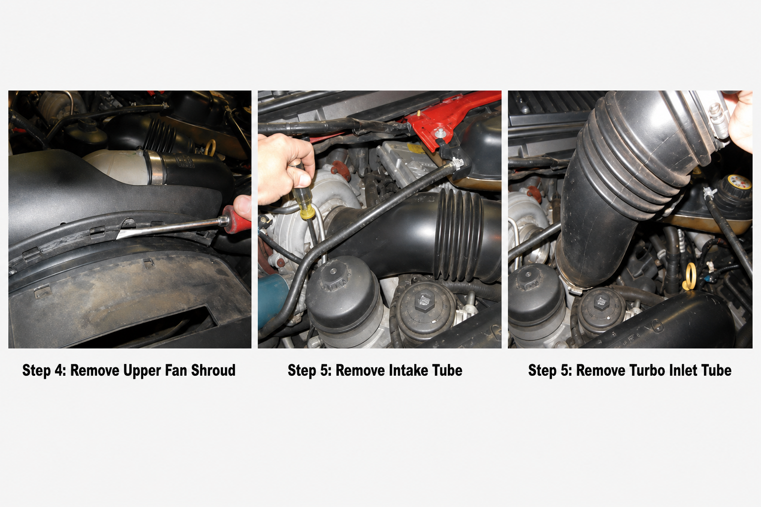
- Remove Intake Piping: Remove the Upper Fan Shroud, Intake Tube, and Turbo Inlet Tube.
- Intake Port Protection: Immediately after removal, seal the intake ports with rags or plugs to prevent screws or debris from falling inside.
4.2 Phase Two: Alternator and Turbo Removal
- Alternator Handling: Remove the alternator mounting bolts and tilt it forward; there is no need to fully remove the belt.
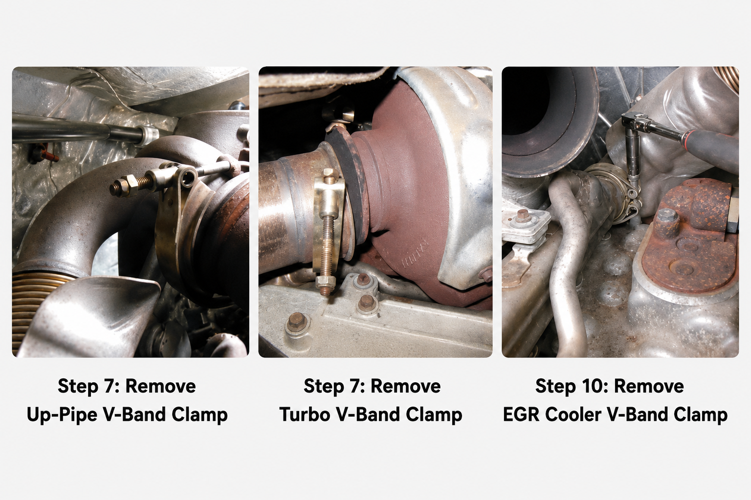
- Turbo Accessory Disconnection: Remove the Intercooler Pipe, Oil Feed Line, and the critical V-band Clamp (exhaust clamp).
- Rust Treatment: Bolts at the Up-pipe and turbo connection are often seized due to high heat; it is recommended to spray WD-40 (penetrating lubricant) in advance to prevent breakage.
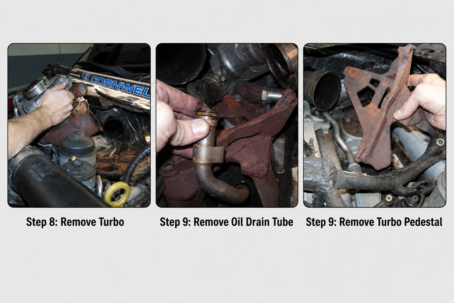
- Turbo Extraction: After confirming the VGT actuator plug is disconnected and all physical connections are free, rotate the Turbo toward the passenger side and remove it.
- Clean the Base: Remove the Turbo Pedestal and Oil Drain Tube, then check the sealing surfaces for carbon buildup.
EGR Cooler Removal and Exhaust Replacement
This phase enters the core of the construction, involving the complete removal of factory hardware and optimization of the exhaust side. Patience is advised as exhaust piping is highly prone to rust and space is limited.
4.3 Phase Three: Factory EGR Cooler Removal
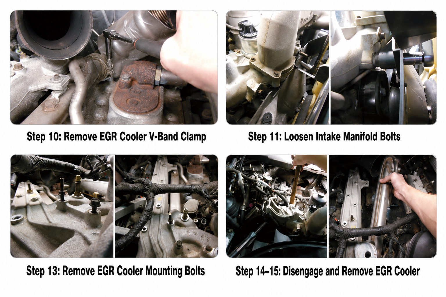
- Disconnect Exhaust: Loosen the V-band Clamp between the EGR Cooler and the factory Up-Pipe. If the clamp is seized, do not force it; apply multiple rounds of penetrating lubricant.
- Loosen Intake Manifold: Loosen the driver-side intake manifold bolts and completely remove the passenger-side bolts to slightly adjust the manifold angle and create space to extract the bulky factory cooler.
- Remove Brackets: Remove the Heater Tube bracket bolt under the alternator and the three main bolts securing the EGR Cooler.
- Extraction: Gently press down on the cooler while lifting the manifold to disengage it from the O-ring seal. Move the old cooler toward the back of the engine and remove it through the front gap.
- Clean Sealing Surfaces: Immediately inspect and remove any residual old O-rings or sealing debris from the manifold interface.
4.4 Intake Manifold Reseating and Suncent Delete Up-Pipe Installation
- Manifold Reseating: Before installing new piping, reseat the intake manifold. Tighten bolts in a cross-pattern from the center outward according to factory torque specs to ensure even pressure.
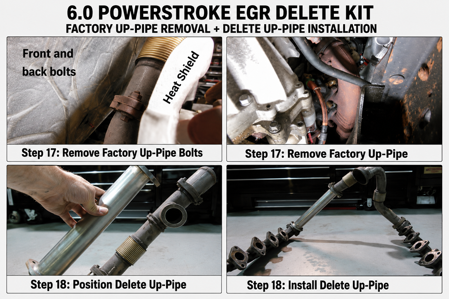
- Remove Factory Up-Pipe: If the kit includes a new pipe, remove the bolts connecting the old pipe to the Exhaust Manifold from the passenger-side underbody. Use correct socket sizes to prevent rounding the bolts in this high-heat zone.
- Install SA Delete Up-Pipe: Place the new pipe and use the metal gaskets provided in the kit.
- Alignment Tip:Do not lock any end immediately. Keep both the exhaust manifold and turbo ends in a "loose fit" state, and tighten them gradually only after everything is perfectly aligned to prevent Exhaust Leaks.
Core Component Reassembly
This phase is the most critical part of the 6.0 Powerstroke EGR Delete Kit installation. You will complete the hardware conversion by establishing the coolant bypass system and sealing the intake ports.
4.5 Installing the Coolant Bypass System
- Hose Pre-assembly: Fit the 3/4" Silicone Hose onto one end of the Stainless Steel Coolant Tube and pre-install the Hose Clamps in a loose state to allow for angle adjustments.
- Physical Connection: Connect the other end of the hose to the Oil Cooler Nipple.
- Routing Optimization: Adjust the stainless steel tube to ensure it does not compress surrounding wiring and maintains a safe clearance from high-temperature exhaust parts to prevent premature hose aging.
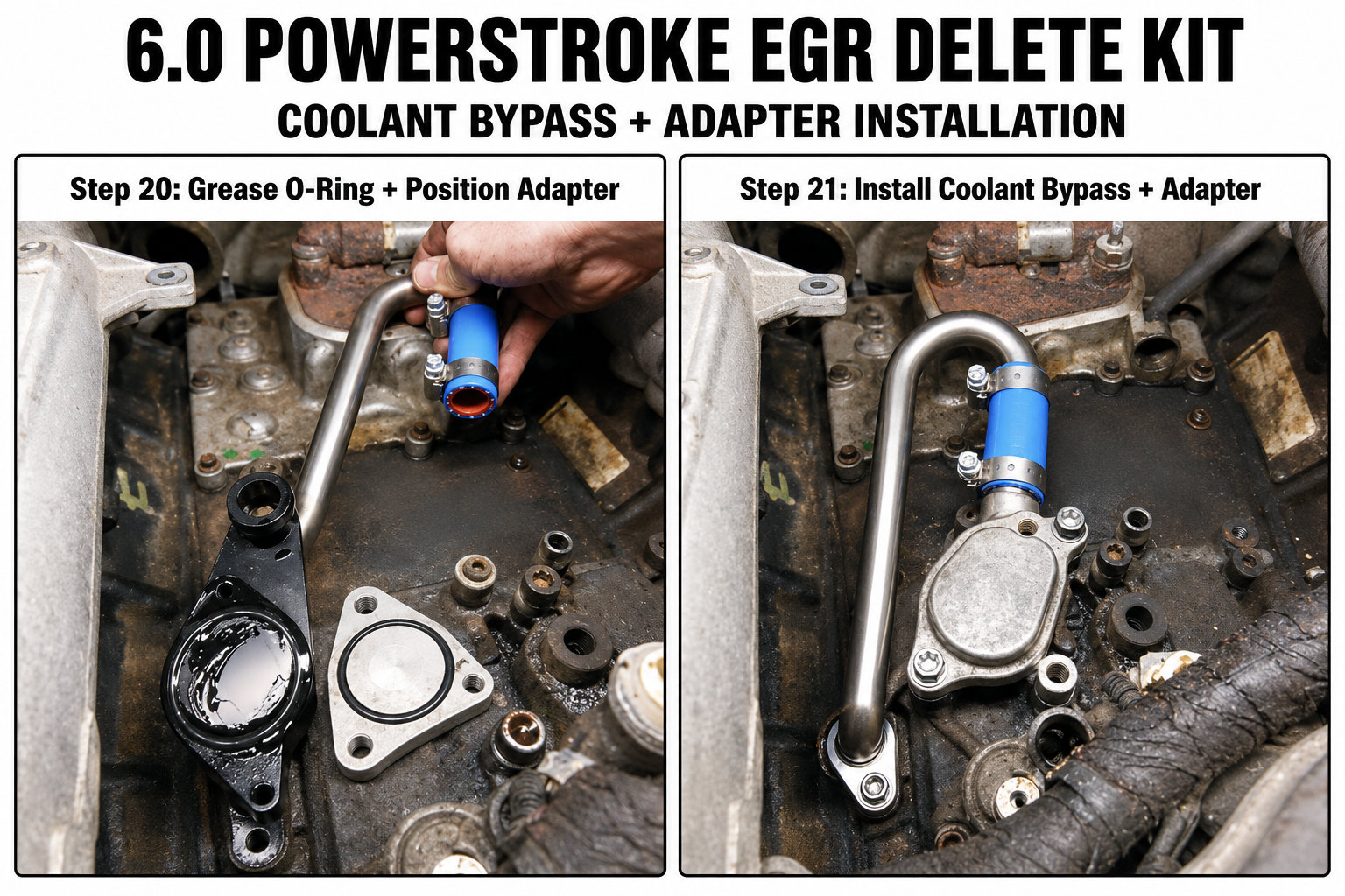
4.6 Installing the EGR Cooler Adapter (Billet Adapter)
- Seal Pre-treatment: Apply a small amount of grease to the new O-ring to prevent cutting or twisting when pressed into the intake manifold.
- Precise Placement: Align the Adapter with the original EGR port on the intake manifold, keep it level, and gently press it in.
- Secure Bolts: Hand-tighten the provided bolts for positioning, then tighten to the specified torque. Do not over-tighten to avoid squeezing out the seal.
4.7 Sealing the Intake Manifold Interface
- Install Closing Plate: Clean the EGR valve opening at the top of the intake manifold to ensure no carbon buildup remains.
- Seal Confirmation: Confirm the gasket or O-ring is properly seated in the groove, then secure the Block-off Plate using factory bolts.
- Final Tightening: Tighten bolts evenly to ensure the plate is flat, preventing any potential Intake Leaks.
Reassembly, Fluid Refill, and Startup Check
After completing the core installation, restore the engine bay layout in the exact reverse order of disassembly. The focus is on eliminating potential leak points and ensuring secure electrical connections.
4.8 Component Reinstallation
- Turbo System: Reseat the Turbo on the pedestal, ensuring the Oil Drain Tube and Oil Feed Line interfaces are surgically clean to prevent lubrication system contamination.
- Clamp Locking: Reinstall V-band Clamps, ensuring they fully engage the flange edges without tilting, which would otherwise cause exhaust leaks.
- Restoration: Reinstall the Alternator, Intercooler Pipe, Fan Shroud, and Intake System in sequence.
- Electrical Check: Reconnect the VGT actuator plug and all sensor connectors, then finally reconnect the negative battery terminals.
4.9 Cooling System Refill and Static Inspection
- Add Coolant: Fill with new coolant meeting factory specs. Fill slowly to minimize Air Pockets.
- Static Leak Test: Before starting, check the two clamps on the Silicone Hose and the area around the Billet Adapter for fluid seepage.
4.10 Startup and Road Test Review
- Idle Observation: Start the engine and idle; listen for abnormal hissing or whistling (indicators of exhaust or intake leaks).
- Level Adjustment: After the engine warms up and the coolant circulates, the level will drop; top off the coolant as needed.
- Short Road Test: Monitor water temperature and Boost Response during a low-load short drive.
- Final Inspection: After the vehicle has completely cooled, re-tighten all hose clamps and confirm that the EGR Cooler Adapter and Up-pipe connections are dry with no soot traces.
V. Critical Installation Pitfalls and Best Practices
The repair space for the 6.0L Powerstroke is narrow and the hardware is complex. Many installation failures stem not from part quality, but from improper handling of details. Below are key points to avoid based on practical experience:
5.1 Preventing Exhaust Leaks
- V-band Clamp Engagement: Exhaust clamps must be perfectly aligned with the flange edges before tightening. If the clamp is skewed, leaks will occur even if the nut is bottomed out, leading to insufficient turbo boost pressure.
- Bolt Pre-treatment: Bolts at the Up-pipe connection are exposed to high temperatures for long periods. You must spray penetrating lubricant (such as WD-40) well in advance of disassembly. Failure to do so often results in broken bolts, significantly increasing repair costs.
5.2 Ensuring Flawless Sealing
- O-ring Protection: When installing the EGR Cooler Adapter, a small amount of grease must be applied to the seal. "Dry" installation can cause the O-ring to cut or roll, leading to coolant leaks that are difficult to detect later.
- Cleanliness First: Before placing new gaskets, you must thoroughly remove carbon deposits and old gasket residue from the intake and exhaust manifold interfaces. This prevents leaks caused by uneven sealing surfaces.
5.3 Scientific Management of Bolts and Debris
- Anti-Contamination Barrier: After removing intake or exhaust manifolds, exposed openings in the engine bay must be immediately plugged with cloth. Even a tiny washer falling in can cause catastrophic damage to high-speed turbo blades or the engine interior.
- Hardware Categorization: The 6.0L engine uses a wide variety of bolts. It is recommended to use labeled parts boxes or cardboard for identification. Never mix bolts of different strengths during reassembly, especially in high-temperature areas prone to thermal expansion.
5.4 Hose Protection and Interference
- Avoiding Heat Sources: Although silicone hoses are heat-resistant, they must never touch the Up-pipe or turbo exhaust housing. After installation, repeatedly verify there is adequate physical clearance between hoses and high-temp components to prevent bursting due to thermal aging.
VI. Post-Installation Diagnostic Trouble Codes (DTCs) and Solutions
After installing the Delete Kit, the ECU may trigger a Check Engine Light due to missing EGR flow or the removal of the EGR valve. Depending on your model year sensitivity, consider the following:
Hardware and Software Integration Options
| Solution Type | Description |
|---|---|
| Basic Hardware Solution | If you already own tuning equipment or your vehicle is less sensitive to flow monitoring, choose the SunCent 3.5" Straight Pipe DPF Delete + EGR Delete Kit with Up-Pipe. This provides both straight pipes and EGR hardware for optimized exhaust flow. |
| Fully Integrated Solution (Recommended for 2005–2007) | Later models have strict ECU strategies and typically require program adjustments to disable monitoring logic. We strongly recommend the SunCent DPF/DEF/EGR All-in-One Kit, which integrates high-quality stainless steel hardware with a matching Tuner for a one-stop solution. |
The "Hardware First" Principle
Note:Tuning only resolves software-level errors. Any physical leaks (coolant or exhaust) caused by improper installation must be fixed by checking hardware connections and cannot be eliminated via programming.