Contents
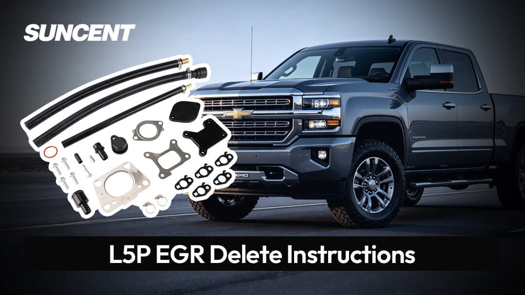
If you are installing an EGR delete kit on a 2017–2025 6.6L Duramax L5P, having clear and organized instructions can make the process much easier. This guide provides step-by-step L5P EGR delete instructions covering the main removal, block-off, coolant bypass, and reassembly procedures. It also highlights key socket sizes, coolant hose routing, model-year differences, and final inspection points to help ensure a cleaner installation.
Visit Product: 2017-2025 6.6L Duramax L5P EGR Delete Kit
For PDF Installation Guide: How to Install the 2017-2025 6.6L Duramax L5P EGR Delete Kit
Important Notice: This L5P EGR Delete Kit is for off-road competition racing vehicles only. It must not be used on emissions-controlled vehicles operated on public roads, streets, or highways in the United States. Any emissions-law risks, fines, warranty issues, or vehicle problems caused by installation or use are the sole responsibility of the purchaser/end user. SuncentAuto is not liable for misuse, illegal use, or improper installation.
Pre-Installation Parts Checklist
Before starting the installation, check that all parts are included and undamaged. The kit should include:
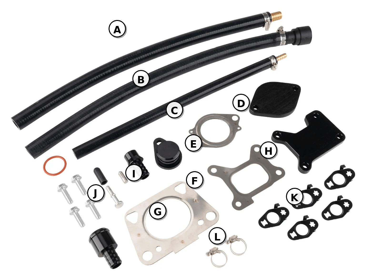
- A — Long silicone coolant hose
- B — Large-diameter heater hose with quick-connect fitting
- C — Small-diameter silicone coolant hose
- D — Black block-off plate
- E — Round metal gasket
- F — Square metal gasket
- G — Metal gasket
- H — Black Y-bridge / bridge fender plate
- I — Billet plug with O-ring
- J — Small caps, bolts, and hardware
- K — Small black sealing gasket set
- L — Hose clamps
Pre-Installation Notes
- Do not work on a hot vehicle. Allow the vehicle to cool completely and always wear safety glasses.
- For older vehicles, spray rust remover such as WD-40 on bolts before removal and wait about 10 minutes.
- After installation, refill the coolant and recheck the coolant level after several heat cycles.
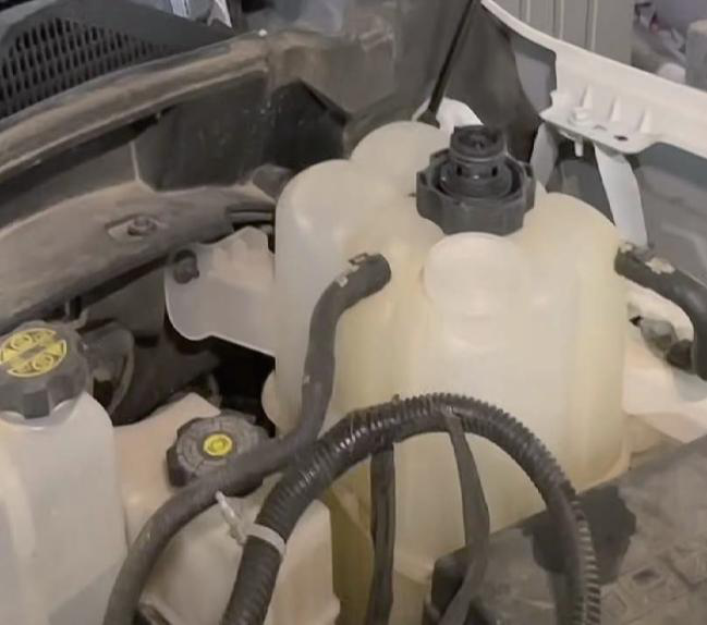
- The coolant reservoir cap is reverse-threaded. When draining coolant, it is recommended not to remove the cap immediately to avoid coolant splashing.
Installation Steps
Step 1. Initial Removal
- Disconnect the negative battery cables from both batteries.
- Remove the passenger-side inner fender liner.
- Remove the plastic drain plug at the lower passenger-side corner of the radiator and drain the coolant.
- Remove the intake pipe and air filter box.
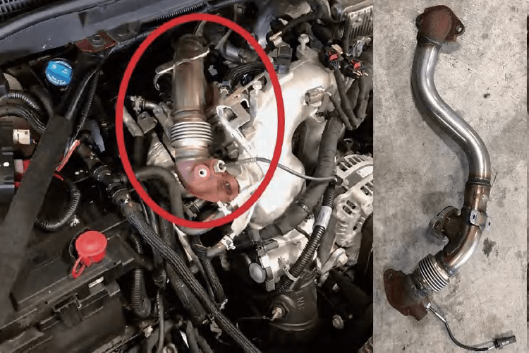
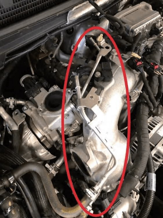
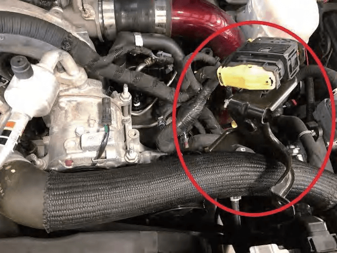
Step 2. Remove the EGR Hot Side Pipe, Turbo Intake Horn, and Y-Bridge Related Parts
- Remove the heat shield from the EGR hot side pipe, then remove the hot side pipe connecting the EGR valve, cooler, and Y-bridge. It is secured by six 13mm bolts.
- Remove the turbo intake horn and PCV hose. The metal clamp on the PCV hose is non-removable. Loosen the clamp first, then pry and pull the hose off.
- Remove the two bolts connecting the intake horn to the turbocharger using a 13mm swivel socket, 1/4" drive, and long extension.
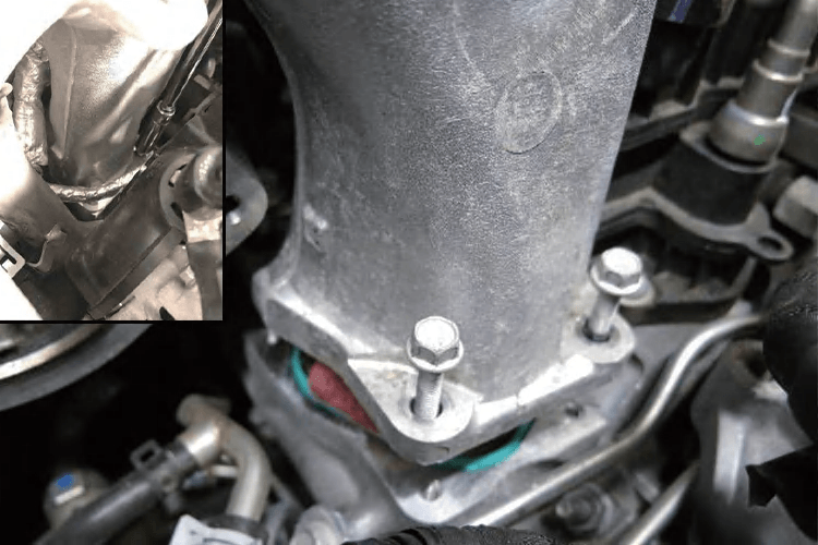
- Remove the small-diameter aluminum coolant hardline on top of the Y-bridge. Remove only the hardline and temporarily leave the hoses in place.
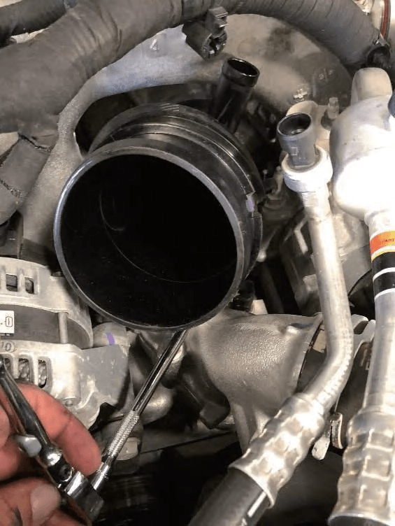
- Remove the 13mm bolt from the plastic cold side pipe support bracket. Rotate and pull down the intercooler pipe to disconnect it from the Y-bridge/throttle blade connection. Cover the opening after removal to prevent debris from entering.
- Disconnect the wiring harness, clips, and throttle blade connector on top of the Y-bridge.
- Use a 1/2" ratchet to release the belt tensioner and remove the serpentine belt from the upper pulleys. The belt does not need to be completely removed.
- Remove the bracket on top of the A/C compressor.
- Remove the four 15mm bolts securing the A/C compressor, then slide the compressor forward toward the fan shroud.
- Use a 10mm socket, 1/4" drive, and long extension to remove the eight bolts securing both sides of the Y-bridge. Remove the Y-bridge. Immediately cover the intake ports with shop rags to prevent debris from falling in. The Y-bridge will be reinstalled later.
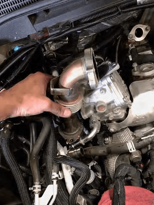
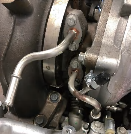
Step 3. Remove the EGR Valve and EGR Cooler
- Remove the heat shield from the short hot side pipe connecting the upper and lower EGR valves, then remove the short pipe secured by four 13mm bolts.
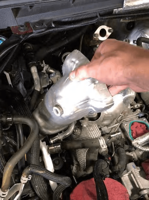
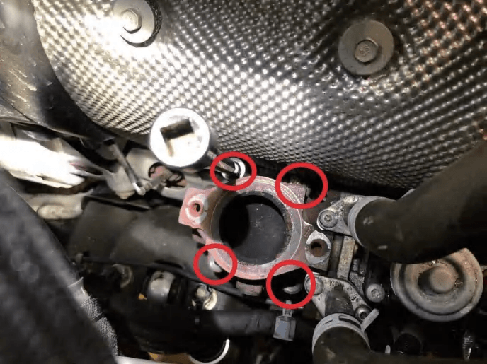
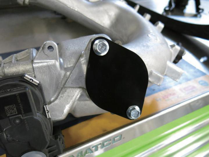
- Disconnect all coolant hoses at the upper EGR valve. Remove the four 13mm bolts/nuts securing the lower EGR valve to the exhaust manifold, then remove the lower EGR valve.
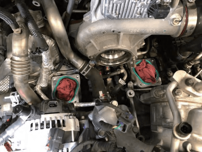
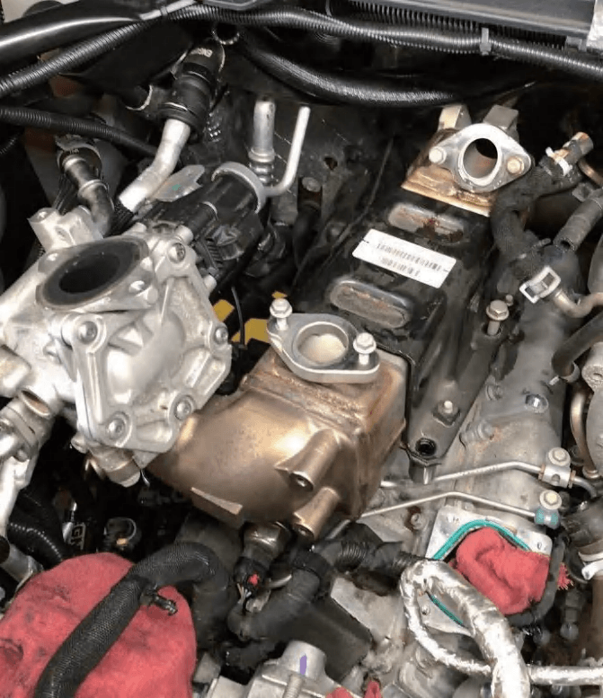
- Install the supplied steel exhaust manifold block-off plate using the new gasket and hardware. Reuse the factory studs/nuts and tighten to the factory torque specification.
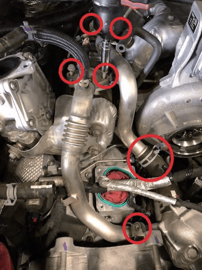
- Remove the two large-diameter steel coolant pipes running from the thermostat housing to the EGR cooler, including one large spring clamp, four 10mm bolts, and one 13mm bolt. Keep the spring clamp near the turbo in place for reuse.
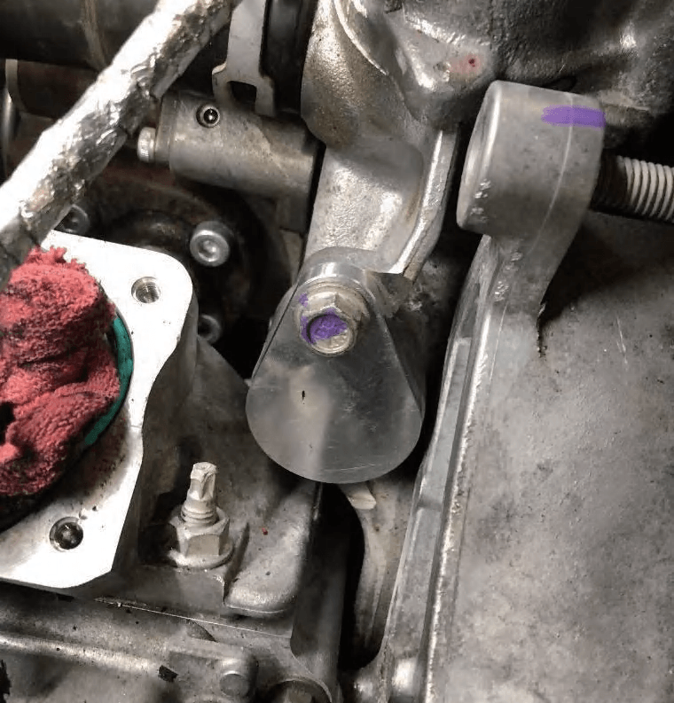
- Apply grease to the O-ring on the billet plug, install it into the coolant port on the thermostat housing, and secure it with the factory bolt.
- Disconnect the small coolant line from the top of the EGR cooler to the turbocharger.
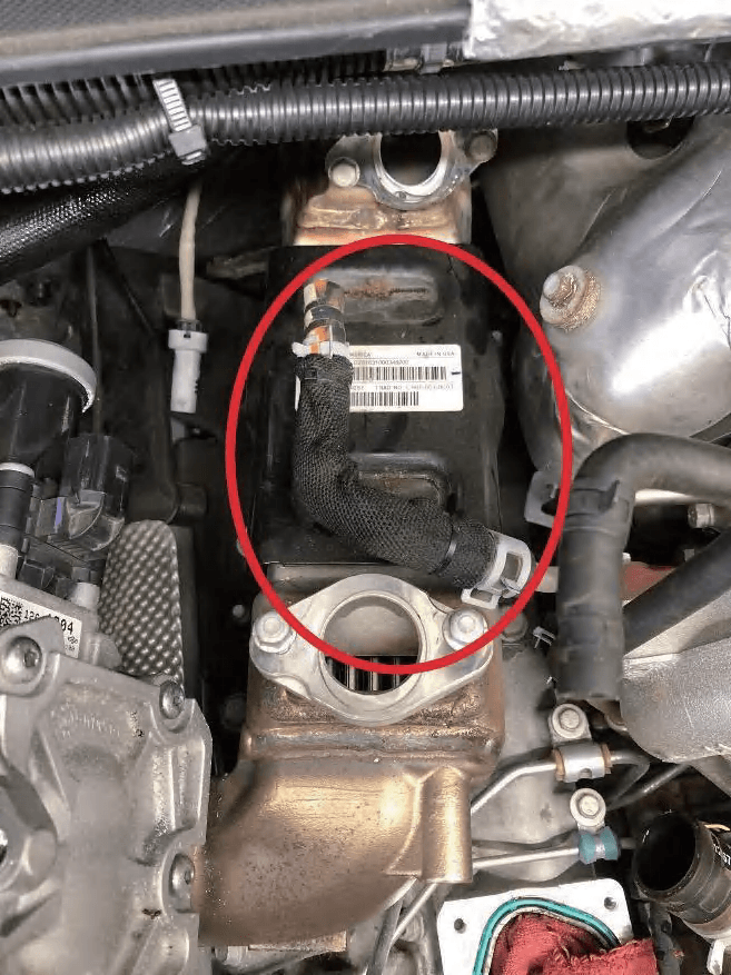
- Remove the five 13mm bolts securing the EGR cooler and remove the cooler assembly.
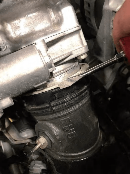
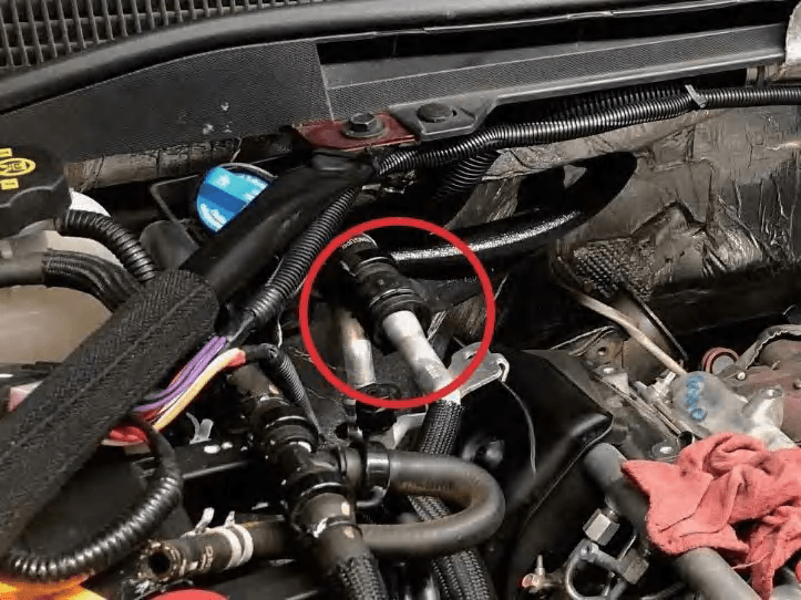
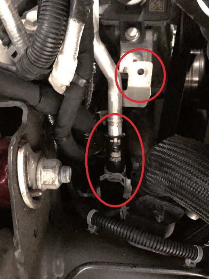
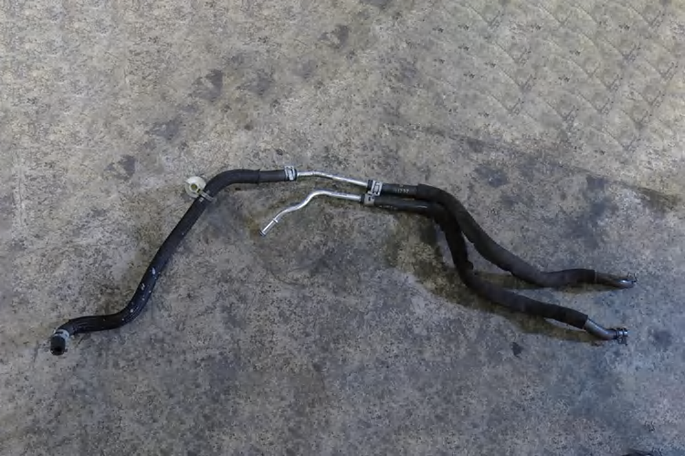
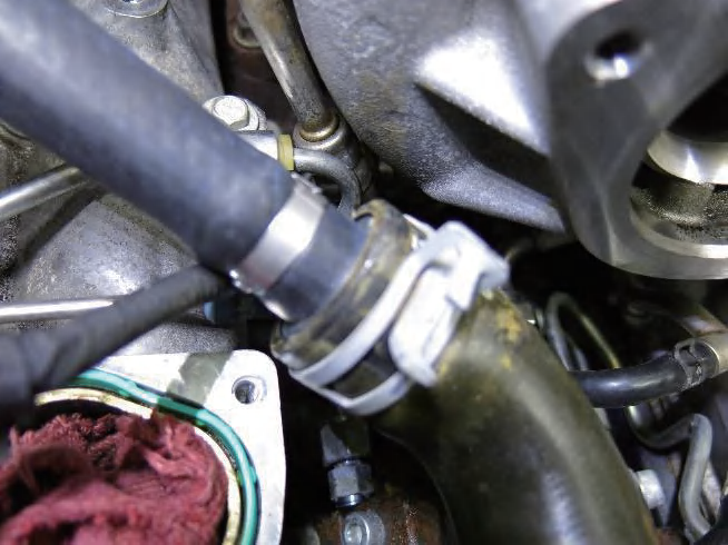
Step 4. Replace the Passenger-Side Coolant Line
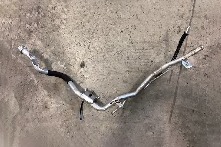
- Remove the passenger-side aluminum coolant tube.
- The upper end connects to the heater core hose at the firewall, and the lower end connects to the lower radiator hose.
- The upper end connects to the heater core hose at the firewall, and the lower end connects to the lower radiator hose. Also disconnect the small coolant line welded to this tube for the urea injector. Keep the lower spring clamp for reuse.
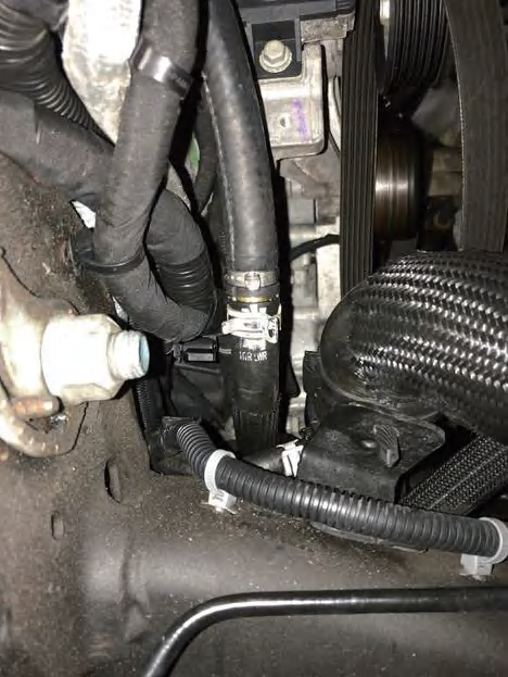
- Install the 20" long, 5/8" hose assembly in place of the original hardline. Connect the brass barb end to the lower factory hose and secure it with the factory spring clamp.
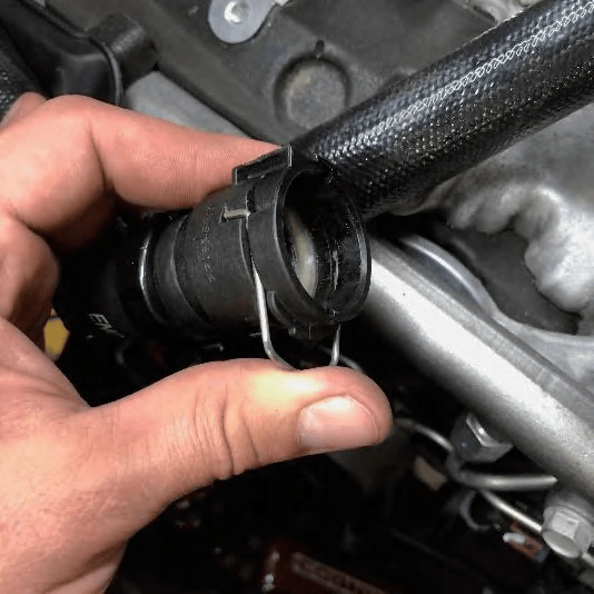
- Connect the upper quick-connect end of the new hose to the heater core hose fitting and push it in until it locks.
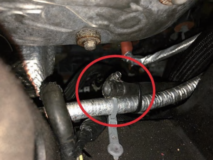
Step 5. Block Off the Urea Injector Coolant Lines
- At the front exhaust elbow below the downpipe, disconnect the small rubber hoses at the urea injector. Remove the related hose/hardline assembly from the side of the engine.
- Insert the 5/16" barbed plug into the rubber hose that was just disconnected and is connected to the large lower radiator hose. Secure it with a clamp and fasten the line with a zip tie.
- The upper end connects to the heater core hose at the firewall, and the lower end connects to the lower radiator hose.
- Use the supplied 1/4" silicone cap and hose clamp to block off the unused coolant port on the coolant supply line leading to the turbocharger center section.
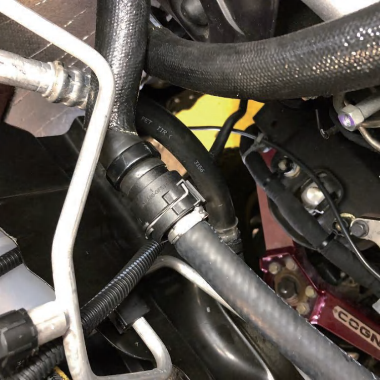
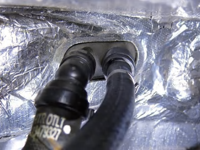
Step 6. Install the New Heater Hose and Model-Year-Specific Coolant Line
- Install the heater hose assembly: connect the quick-connect end to the heater core fitting on the firewall.
- Connect the 1.3" aluminum barb end to the hose near the thermostat housing/turbo area and secure it with the factory spring clamp.
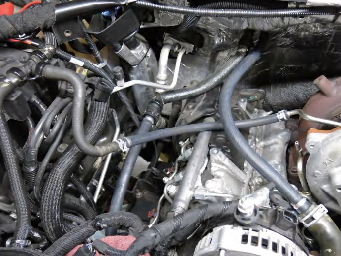
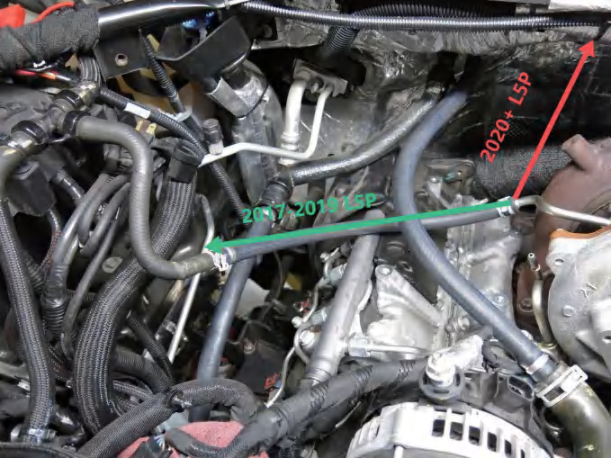
- Route the turbo coolant line according to model year:
- 2017–2019: Install the supplied 15" long, 3/8" coolant line. One end connects to the upper turbo coolant line, and the brass barb end connects to the factory coolant line near the battery that leads to the coolant reservoir hose.
- 2022+: Reroute the turbocharger coolant line to the coolant overflow tank as shown.
Step 7. Reassembly and Inspection
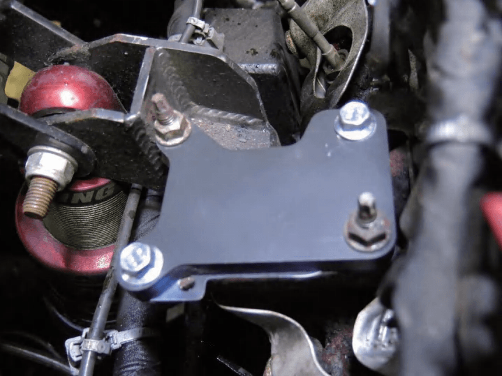
- Install the bridge fender onto the Y-bridge using the supplied 8mm flange bolts and washers, then tighten to the factory torque specification.
- Reinstall the radiator drain plug and refill the coolant.
- Reinstall the intake assembly.
- Reinstall the inner fender liner.
- Start the vehicle and let it idle to check for leaks. The cooling system may need several heat cycles to fully purge air, so coolant may need to be topped off once or twice afterward.
Final Checklist
- All shop rags have been removed from the intake ports.
- All coolant hoses, plugs, silicone caps, and clamps are secured.
- The Y-bridge, A/C compressor, belt, intake assembly, and inner fender liner have been reinstalled.
- Coolant has been refilled, and there are no leaks after heat cycling.
- The negative battery cables have been reconnected.
Post-Installation Notes - Tuning Required
After installing an EGR delete kit, an appropriate ECU tune is typically required. Because the factory engine control system is designed to monitor the EGR valve, EGR cooler, sensors, and related emissions components, removing or blocking these parts may trigger fault codes, check engine lights, limp mode, or drivability issues if the vehicle is not properly tuned.
Read also : What Happens If You Don't Tune the ECU After an EGR/DPF Delete?
Conclusion
Installing an L5P EGR delete kit requires careful disassembly, proper coolant line routing, and attention to sealing points. The most important steps include removing the EGR valve and cooler, installing the supplied block-off plates and gaskets, rerouting or capping the appropriate coolant lines, and checking the system thoroughly after reassembly.
Once the installation is complete, refill the coolant, inspect all hoses, plugs, caps, clamps, and fittings, and let the truck idle while checking for leaks. Because air may remain in the cooling system, it is normal to recheck and top off the coolant after several heat cycles. Following these L5P EGR delete instructions carefully can help ensure a secure installation and reduce the chance of leaks or loose connections.