Contents
- 1. Confirm the Truck and Kit Before Installation
- 2. Check the Package Contents Before Disassembly
- 3. Prepare the Tools and Work Area
- 4. Inspect the Truck Before Installation
- 5. Recommended Installation Workflow
- 6. 2017 F-250 Delete Kit Installation Difficulty
- 7. Common Installation Problems and Troubleshooting
- 8. DIY or Professional Installation?
- 9. Final Installation Checklist
- Conclusion
- Official SuncentAuto Installation Manuals
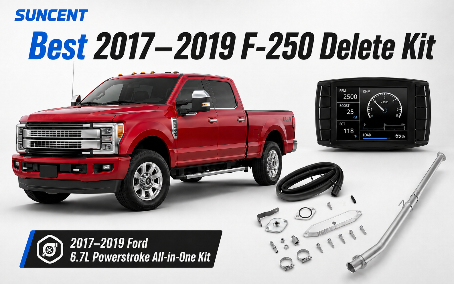
Installing a 6.7 Powerstroke delete kit on a 2017 Ford F-250 involves more than replacing a single exhaust pipe. A complete project normally includes three main areas: a Race Pipe or Downpipe-back exhaust installed underneath the truck, EGR-related plates, fittings, hoses, and seals installed in the engine bay, and a compatible tuning device with calibration files, such as EZ LYNK or Mini Maxx V2.
For this reason, the first step is not removing factory parts. The first step is confirming the vehicle information, package contents, exhaust layout, and tuning support. This guide focuses on installation preparation, workflow, common problems, and final inspection for a 2017 F-250 pickup. Exact bolt locations, torque specifications, coolant routing, and device procedures must come from the instructions supplied with the specific product.

1. Confirm the Truck and Kit Before Installation
1.1 Confirm the Vehicle Information
This guide primarily applies to:
- 2017 Ford F-250 Super Duty
- 6.7L Power Stroke diesel engine
- Pickup models
A product description that only says “Fits Ford 6.7L Power Stroke” is not enough to confirm compatibility. Before ordering parts or disassembling the truck, verify the following information.
| Vehicle Information | Why It Matters |
|---|---|
| Pickup or Cab & Chassis | Frame design and exhaust routing may differ. |
| Cab configuration | The cab may affect wheelbase and exhaust length. |
| Bed length | Bed length can affect rear pipe length and hanger position. |
| Wheelbase | Some exhaust sections are specific to wheelbase. |
| 2WD or 4WD | Drivetrain layout may affect available installation space. |
| Single or dual rear wheels | Rear exhaust routing may differ. |
| Factory or modified exhaust | This determines how the new exhaust will connect. |
| Current tuning status | This helps prevent device, file, or calibration conflicts. |
| Existing diagnostic trouble codes | This helps separate pre-existing faults from installation-related problems. |
If you have not yet selected a Race Pipe, Downpipe-back exhaust, 4-inch or 5-inch system, or tuning platform, review our 2017–2019 F-250 delete kit buying guide .
1.2 Confirm the Exhaust Configuration
Common 2017 F-250 packages are built around either a Race Pipe or a Downpipe-back exhaust system.
| Exhaust Type | Coverage | What to Confirm Before Installation |
|---|---|---|
| Race Pipe | Replaces a specified section of the factory exhaust. | Confirm which factory sections remain in place. |
| Downpipe-back | Runs from behind the downpipe to the tailpipe. | Confirm wheelbase, bed length, and hanger locations. |
| 4-inch exhaust | Uses 4-inch pipes and clamps. | All pipes, clamps, and adapters must use the same diameter. |
| 5-inch exhaust | Uses larger-diameter tubing. | Carefully check clearance around the frame, suspension, and spare tire. |
| Exhaust with muffler | Includes a muffler section. | Confirm the muffler direction and available underbody space. |
| Exhaust without muffler | Uses a simpler pipe layout. | Consider expected noise and in-cab drone before installation. |
A Race Pipe is not the same as a complete rear exhaust system. If a Race Pipe package is mistaken for a full Downpipe-back system, the installer may discover that the expected rear pipe sections are not included.
Four-inch and 5-inch exhaust parts must not be mixed. Pipes, clamps, mufflers, and adapters must all belong to the same diameter system.
1.3 Confirm the EGR-Related Hardware
Engine-bay hardware may include:
- Plates or brackets
- Fittings
- Hoses
- Gaskets and seals
- Clamps
- Fasteners
- Product-specific accessories
Before installation, confirm:
- The product is specifically listed for the 2017 model year.
- All required seals, fittings, and hoses are included.
- Whether any factory parts must be reused.
- The actual hardware differences between available kit versions.
- Whether product-specific installation instructions are provided.
Hardware from different brands may look similar but use different fittings, hose arrangements, sealing methods, or installation sequences. Do not use torque values or coolant-routing information from another brand or engine platform.
1.4 Confirm the Tuning Device and Calibration Files
The tuning device, calibration files, and technical support may be sold separately. Before installation, confirm:
- The device supports a 2017 Ford F-250 with the 6.7L Power Stroke.
- The device is not locked or linked to another vehicle or account.
- The required tune files are included.
- Engine and transmission support are both included, if required.
- The identity of the tuning provider.
- Whether future revisions or technical support are included.
- Whether device setup must be completed before or after hardware installation.
- What type of battery support is required during programming.
EZ LYNK users can review our EZ LYNK Auto Agent installation guide .
Mini Maxx V2 users can review our Mini Maxx V2 installation instructions .
Do not guess whether tuning should be completed before or after the hardware work. Different devices, calibration files, and tuning providers may require different procedures.
2. Check the Package Contents Before Disassembly
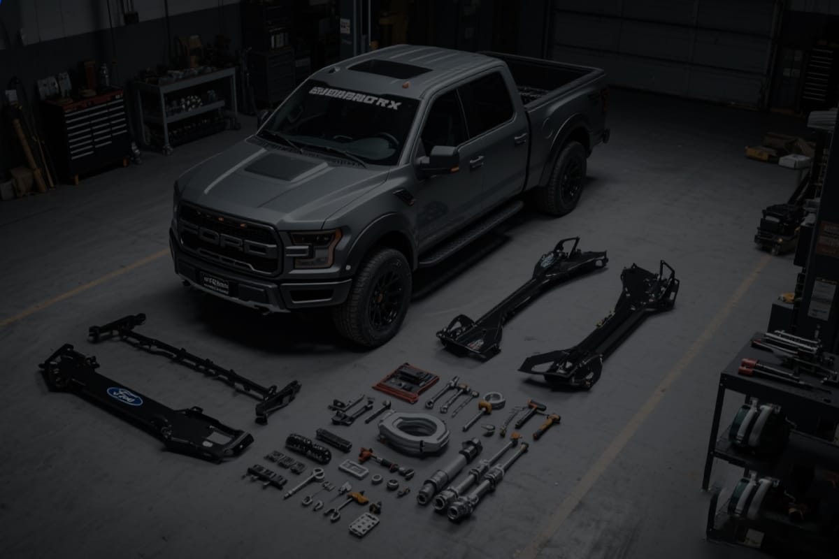
After receiving the kit, lay out all parts and compare them with the order details, product listing, and packing list. If you are comparing a complete package rather than purchasing the exhaust, engine-bay hardware, and tuning components separately, review the listed contents of each diesel delete kit carefully before beginning the installation.
| Part Category | What to Check |
|---|---|
| Exhaust pipes | Diameter, length, bends, and connection style |
| Engine-bay hardware | Model-year range, version, and intended position |
| Clamps | Quantity, size, and visible damage |
| Gaskets and seals | Missing, cracked, folded, or crushed parts |
| Hoses and fittings | Quantity, connection style, and size |
| Fasteners | Thread condition and completeness |
| Tuning device | Model, cables, and accessories |
| Tuning service | Whether the required files have been delivered |
| Installation instructions | Printed instructions or product-specific PDF |
Do Not Rely Only on the Main Product Image
A product image may show the exhaust, EGR hardware, and tuning device, while the selected variation includes only part of that package.
Check the written order details for:
- Whether a tuner is included
- Whether tune files are included
- Whether a muffler is included
- Whether the package contains a complete Downpipe-back exhaust
- Whether all clamps and gaskets are included
- Whether all required fittings are included
Inspect for Shipping Damage
Check for:
- Crushed pipe ends
- Bent flanges
- Cracks near welds
- Damaged threads
- Broken gaskets
- Damaged electronic devices or cables
If parts are missing or damaged, contact the seller before disassembling the truck. Installed, programmed, or visibly used products may be subject to different return conditions.
3. Prepare the Tools and Work Area
Exact socket and wrench sizes vary by product. Use the product instructions to confirm specific requirements. A complete project generally requires the following tool categories.
Basic Hand Tools
- Metric socket and wrench set
- Ratchets and extensions
- Torque wrench
- Screwdrivers
- Pliers
- Connector-removal tools
- Work light
Exhaust Removal Tools
- Penetrating oil
- Exhaust hanger removal tool
- Suitable impact tools
- Exhaust support stand
- Rubber mallet
- Wire brush
Fluids and Cleaning Supplies
- Drain pan
- Coolant that meets the vehicle requirements
- Clean shop towels
- Protective caps for open ports
- Parts-cleaning supplies
- New gaskets and seals
Safety Equipment
- Safety glasses
- Work gloves
- Wheel chocks
- Approved vehicle lift or jack stands
- Fire extinguisher
- Adequate ventilation
Never work underneath a truck supported only by a floor jack. The factory exhaust assembly is large and heavy. Support it with a separate stand before removing its connections.
Tuning Preparation
Depending on the device, you may also need:
- Stable battery support
- Smartphone or tablet
- Reliable internet access
- Correct account information
- Vehicle VIN
- Tuning-provider contact information
4. Inspect the Truck Before Installation
4.1 Save Existing Diagnostic Trouble Codes
Before disassembly, scan and save the current diagnostic trouble codes. Also record:
- Warning lights on the instrument cluster
- Current tuning status
- Coolant level
- Existing exhaust leaks
- Starting, charging, or communication problems
This information helps separate pre-existing faults from problems that appear after installation.
If the truck already has several undiagnosed faults, do not assume that installing new hardware will automatically correct them. Work trucks should receive a basic mechanical and electrical diagnosis before additional modifications are introduced.
4.2 Check for Existing Leaks
Inspect the following areas:
- Coolant system
- Engine oil system
- Fuel system
- Exhaust connections
- Intake connections
Calibration software cannot repair a physical leak. Existing coolant seepage, damaged exhaust joints, or deteriorated hoses should be diagnosed before installation.
4.3 Inspect for Corrosion
A 2017 F-250 may have experienced years of heat cycles, rain, snow, farm mud, coastal salt air, or winter road salt. Closely inspect:
- Exhaust clamps
- Flange bolts
- Exhaust hangers
- Areas around sensor threads
- Fasteners in high-temperature engine-bay locations
Severe corrosion can cause:
- Clamps that cannot be loosened
- Pipes that are seized together
- Broken bolts
- Damaged threads
- Significantly longer installation time
Apply penetrating oil in advance where appropriate and allow additional time for broken-fastener or thread-repair work.
4.4 Photograph the Factory Layout
Before removing parts, photograph:
- Wiring routes
- Hose routes
- Clamp orientation
- Hanger positions
- Pipe connection order
- Factory component orientation
Place removed bolts, clamps, and brackets in labeled bags. For a multi-stage project, reference photos and labels can prevent confusion during reassembly.
5. Recommended Installation Workflow
The following section explains the general workflow for a complete project. It does not replace product-specific, step-by-step instructions.
Phase 1: Read All Instructions
Before removing any factory parts, read:
- Exhaust-system instructions
- EGR-related hardware instructions
- Tuning-device instructions
- Tuning-provider requirements
- Packing list
- Product return policy
Do not treat a video for another brand or engine as an exact service manual. Videos may help explain the general work area, but they cannot confirm the pipe orientation, sealing requirements, or fastener specifications for your product.
Phase 2: Confirm the Tuning Workflow
Before hardware removal, confirm that:
- The device can identify and communicate with the truck.
- The account and VIN status are correct.
- The required calibration files have been delivered.
- All device cables and accessories are present.
- The battery and charging system meet the programming requirements.
- You know whether the original vehicle file must be saved.
- You know when the calibration must be installed.
- You know whom to contact if programming fails.
This prevents the truck from being partially disassembled before an unsupported device, inactive account, missing file, or additional service charge is discovered.
Phase 3: Prepare the Truck
- Park the truck on a level, well-ventilated surface.
- Allow the engine and exhaust to cool completely.
- Chock the wheels.
- Raise and support the truck with approved equipment.
- Support the exhaust section that will be removed.
- Label wiring, hoses, and electrical connectors.
- Prepare a drain pan and covers for open ports.
Do not work on hot exhaust parts, fittings, or coolant-system components.
Phase 4: Exhaust-Side Installation
Race Pipe Installation Considerations
Before installing a Race Pipe, identify the exact factory section it replaces and which front and rear exhaust sections remain.
Important installation checks include:
- Support the factory pipe before disconnecting it.
- Confirm that all related wiring, brackets, and connections are free.
- Compare the new and old pipe lengths and bend directions.
- Inspect the new pipe ends for deformation.
- Leave all clamps loose during initial fitment.
- Complete the full alignment before final tightening.
- Check clearance around the frame, suspension, driveline, and spare tire.
If the new pipe is clearly too long, too short, or incorrectly angled, do not force the exhaust into position or bend the hangers. Recheck the model year, pipe orientation, and selected product variation.
Downpipe-Back Installation Considerations
A Downpipe-back system normally contains several sections. Before installation, identify:
- Front pipe
- Mid-pipe
- Muffler, if included
- Tailpipe
- Matching clamps and hangers
The system can be loosely positioned from front to rear, but do not fully tighten the front clamps before confirming the final tailpipe position.
Premature tightening may cause:
- The rear exhaust to shift to one side
- Excessive hanger tension
- Tailpipe contact with the body
- Insufficient clearance around the frame or spare tire
After completing the alignment, check:
- Whether the hangers sit in a natural position
- Whether the muffler is installed in the correct direction
- Whether the tailpipe is centered
- Whether the exhaust touches the chassis
- Whether all slip joints are fully engaged
- Whether the system is under visible tension
4-Inch vs. 5-Inch Installation Considerations
A 5-inch exhaust does not necessarily use a completely different installation method, but the larger tubing generally requires more careful clearance checks.
| Inspection Item | 4-Inch Exhaust | 5-Inch Exhaust |
|---|---|---|
| Pipes and clamps | All parts must be 4-inch. | All parts must be 5-inch. |
| Underbody space | Usually provides more clearance. | Requires more careful clearance checks. |
| Tailpipe position | Still requires full-system alignment. | More sensitive to pipe angle. |
| Space near the spare tire | Must be checked. | Requires particular attention. |
| Muffler size | Usually more compact. | May require more underbody space. |
Do not select an exhaust diameter based only on appearance or sound. Available space, normal vehicle use, and expected in-cab drone should also be considered.
Phase 5: Engine-Bay Installation
Engine-bay work can be divided into the following stages:
- Remove covers or components that restrict access.
- Handle coolant according to the product instructions.
- Remove the specified factory hardware.
- Install the supplied plates, brackets, or fittings.
- Route hoses according to the product instructions.
- Inspect sealing surfaces and connections.
- Reinstall wiring, brackets, and surrounding components.
During this work:
- Cover all open ports immediately.
- Prevent dirt, metal particles, or loose fasteners from entering openings.
- Do not reuse damaged gaskets unless the product instructions allow it.
- Do not kink hoses.
- Keep wiring away from exhaust components and other heat sources.
- Keep hoses and wiring away from belts, fans, and moving parts.
- Do not copy coolant-routing information from another engine platform.
For help identifying the correct hardware version, review our 6.7 Power Stroke EGR kit specification guide .
Phase 6: Reassembly
After completing the exhaust and engine-bay work, confirm that:
- All wiring is secured.
- No hoses are kinked.
- All openings are properly connected or sealed.
- Clamps and flanges are positioned correctly.
- Exhaust hangers are not under abnormal tension.
- The exhaust does not contact the frame or body.
- All tools, caps, and shop towels have been removed.
- Required fluids have been restored.
- The tuning workflow has been completed according to the provider’s instructions.
Do not rely on memory for the final inspection. Compare the finished work with the packing list and the photos taken before disassembly.
Phase 7: Initial Operation and Inspection
During the first low-load operation, check for:
- Exhaust leaks
- Coolant leaks
- Metal-to-metal contact
- Abnormal vibration
- Tuning-device communication errors
- New diagnostic trouble codes
Do not immediately use the truck for heavy towing after installation. Complete the initial inspection, allow the truck to go through a heat cycle, and then recheck fluid levels, clamps, and exhaust position.
6. 2017 F-250 Delete Kit Installation Difficulty
| Installation Area | Relative Difficulty | Main Variables |
|---|---|---|
| Tuning-device preparation | Varies by platform | Account status, files, communication, and battery support |
| Race Pipe | Moderate | Factory connections and corrosion |
| Downpipe-back exhaust | Moderate | Pipe sections, hangers, and tailpipe alignment |
| Engine-bay hardware | Moderate to high | Access, coolant handling, and fasteners |
| Complete package | High | Coordination between multiple systems and missing-part risk |
There is no single installation time that applies to every truck. Actual labor time depends on:
- Corrosion level
- Access to a vehicle lift
- Installer experience
- Race Pipe or complete exhaust configuration
- Broken fasteners
- Previous vehicle modifications
- Whether the tuning device and files are prepared in advance
First-time DIY installers should not plan the project based only on the length of an installation video. Vehicle condition, available tools, installer experience, and video editing can make the real project take much longer.
7. Common Installation Problems and Troubleshooting
7.1 The New Exhaust Does Not Line Up
Check the following:
- Is the product listed for the 2017 model year?
- Was a pickup kit confused with a Cab & Chassis kit?
- Was a Race Pipe confused with a Downpipe-back system?
- Were 4-inch and 5-inch parts mixed?
- Is a pipe installed backward?
- Is a hanger facing the wrong direction?
- Were the front clamps tightened too early?
- Was the factory exhaust previously modified?
If every connection has already been fully tightened, loosen the appropriate joints according to the product instructions and realign the complete system. Do not force, bend, or cut a clearly incompatible component.
7.2 Exhaust Leak at a Clamp or Joint
Inspect:
- Pipe insertion depth
- Clamp position
- Cleanliness of the connection surface
- Pipe-end deformation
- Clamp diameter
- Excessive tension in the exhaust system
- Damaged flanges or seals
Do not apply sealant unless the product manufacturer specifically recommends it. Some materials are unsuitable for high-temperature locations and may make future removal more difficult.
7.3 Exhaust Rattle or Drone
Check clearance around:
- Frame rails
- Crossmembers
- Driveline components
- Suspension components
- Spare tire
- Body panels
- Tailpipe outlet
If an exhaust hanger is visibly stretched or twisted, the complete system may not be naturally aligned. Loosen the appropriate connections, reposition the pipes, and then retighten them according to the instructions.
7.4 The Tuning Device Is Present, but the Files Are Missing
The tuning device does not necessarily include calibration files. Review the order and confirm:
- Tuning-device model
- VIN and vehicle support
- Engine calibration files
- Transmission support
- Service duration
- Tuning-provider contact information
Do not repeatedly install files from an unknown source or files that do not match the vehicle and hardware configuration.
7.5 EZ LYNK Cannot Connect
Check:
- OBD-II connection
- Phone Wi-Fi settings
- App account status
- VIN association
- Auto Agent power
- Whether the tuning provider has sent the required files
- Vehicle battery condition
For a more detailed setup process, see our EZ LYNK Auto Agent installation guide .
7.6 Mini Maxx V2 Stops, Restarts, or Loses Communication
Check:
- Battery voltage
- Stable battery support
- OBD-II connection
- Other devices connected to the diagnostic port
- Selected vehicle and engine
- Device cables and accessories
- File version
For additional troubleshooting, see our Mini Maxx V2 troubleshooting guide .
7.7 Coolant Leak After Engine-Bay Work
Inspect:
- Hoses
- Fittings
- Clamps
- Gaskets
- Sealing surfaces
- Coolant level
- Possible trapped air in the cooling system
A physical coolant leak cannot be repaired through tuning. If the leak continues or the coolant level drops quickly, stop operating the truck and correct the mechanical problem.
7.8 A Fastener Breaks During Removal
Do not continue forcing the component after a bolt breaks or threads are damaged.
First:
- Protect all open ports.
- Identify the exact break location.
- Determine whether extraction is required.
- Inspect the threads for possible repair.
- Confirm that you have the correct tools and experience.
If the broken fastener is near a sealing surface, high-temperature component, or difficult-to-access area, professional repair is usually the safer choice.
8. DIY or Professional Installation?
DIY May Be Reasonable When
- You have approved vehicle lifting and support equipment.
- You have experience removing and installing exhaust systems.
- You understand diesel-engine cooling systems.
- You can correctly use a torque wrench.
- You have experience with corroded fasteners and connections.
- You have the complete product instructions.
- The tuning device and files have been confirmed.
- The truck can remain out of service if the project takes longer than expected.
Professional Installation Is Recommended When
- The truck cannot remain out of service for an extended period.
- The exhaust or fasteners are severely corroded.
- The truck has multiple undiagnosed trouble codes.
- Coolant, fuel, or exhaust leaks are already present.
- The vehicle was previously modified by another owner or shop.
- The current calibration status is unknown.
- The received kit does not match the product description.
- A bolt has broken or threads are damaged.
- Safe lifting and support equipment is unavailable.
For a work truck, the installation price is not the only cost. Waiting for missing parts, repairing broken fasteners, or resolving tuning problems after the truck is disassembled may create significant downtime.
For a broader cost breakdown, review our 6.7 Power Stroke project cost guide .
9. Final Installation Checklist
Exhaust System
- All pipes face the correct direction.
- Clamps and flanges are positioned correctly.
- Slip joints are fully engaged.
- Exhaust hangers sit naturally.
- The exhaust does not contact the frame, suspension, or driveline.
- The tailpipe clears the spare tire and body.
- No obvious exhaust leaks are present.
- No metal contact or rattling is present.
Engine Bay
- Hoses and fittings are secured.
- Wiring is routed away from heat sources.
- Hoses are clear of belts and fans.
- Coolant level is correct.
- No coolant leaks are present.
- All open ports have been connected or sealed.
- All tools, caps, and shop towels have been removed.
Tuning Device
- VIN and vehicle information are correct.
- The correct calibration file is installed.
- No communication or programming errors are present.
- The original vehicle file has been saved, when required.
- Tuning-provider contact information has been saved.
Follow-Up Inspection
- The initial low-load inspection has been completed.
- Coolant level has been rechecked after a heat cycle.
- Clamps and joints have been rechecked as required.
- No new noises are present.
- No new leaks are present.
- No unexpected diagnostic trouble codes are present.
- Factory parts have been labeled and stored.
Conclusion
Exhaust parts that do not align, an unknown tuning status, ongoing leaks, severe corrosion, and broken fasteners are all reasons to pause the installation and reassess the project. Careful preparation, correct exhaust alignment, and a complete final inspection are more important than finishing the installation as quickly as possible.
Official SuncentAuto Installation Manuals
This article provides a general installation-planning workflow. For product-specific component locations, preparation requirements, diagrams, and installation steps, use the official SuncentAuto manual that matches the exact kit installed on the truck. Always confirm the product variation and model-year range before beginning work.
- Browse All SuncentAuto Installation Guides
- 2011–2022 6.7L Power Stroke Race Pipe Installation Manual (PDF)
- 2011–2022 Ford 6.7L Power Stroke 4-Inch/5-Inch Downpipe-Back Exhaust Installation Manual (PDF)
- 2011–2023 Ford 6.7L Power Stroke EGR Kit Installation Manual (PDF)
- 2011–2025 Ford 6.7L Power Stroke PCV/CCV Reroute Kit with Catch Can Installation Manual (PDF)