 Contents
Contents
- Important Emissions Compliance Notice
- Choosing the Correct LML Duramax Delete Kit
- Complete the Tuning Before Removing Hardware
- Tools Required for LML Duramax Delete Kit Installation
- Disconnect the Three Required Engine Connectors
- Removing the Factory Exhaust System
- Disconnect Factory Exhaust Sensors and Wiring
- Remove the Factory Exhaust Assembly
- Remove the Factory DEF Components (Optional)
- Prepare Passenger-Side Access for EGR and Up-Pipe Work
- Remove the DEF Fill Neck
- Raise the Passenger Side of the Cab for Additional Clearance
- Drain the Engine Coolant
- Remove Intake Components for EGR Access
- Remove the Factory EGR System
- Remove the Factory Up-Pipe
- Install the Replacement Up-Pipe
- Reroute the Coolant System After EGR Cooler Removal
- Reinstall the Intake System
- Lower the Cab and Complete Engine Bay Assembly
- Refill Coolant and Perform Initial Testing
- Install the Replacement Exhaust System
- Option 1: Install DPF Replacement Pipes
- Option 2: Install Full 5-Inch Exhaust System
- Final Inspection Checklist
- Installation Guides & Technical Manuals
- Related Resources
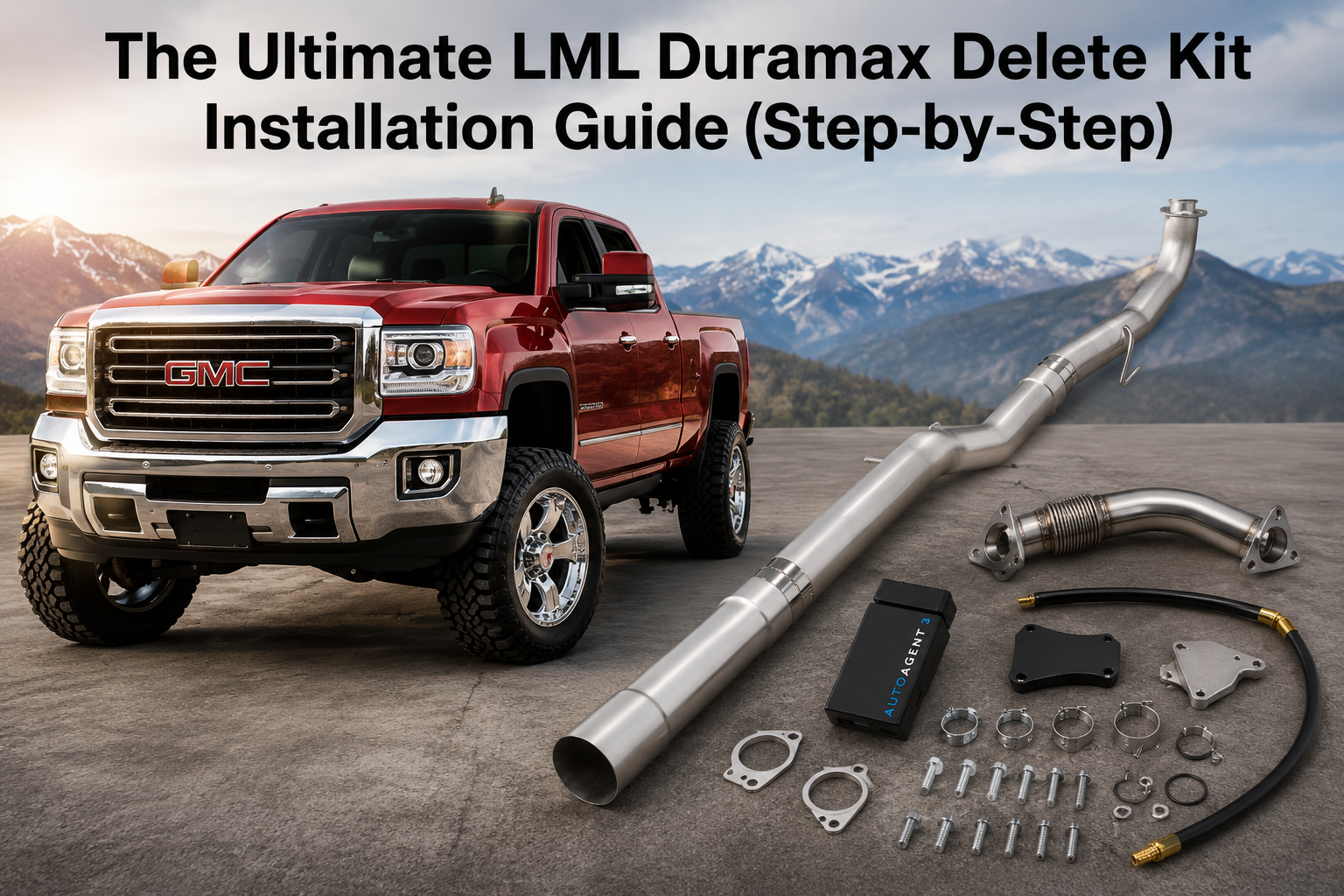
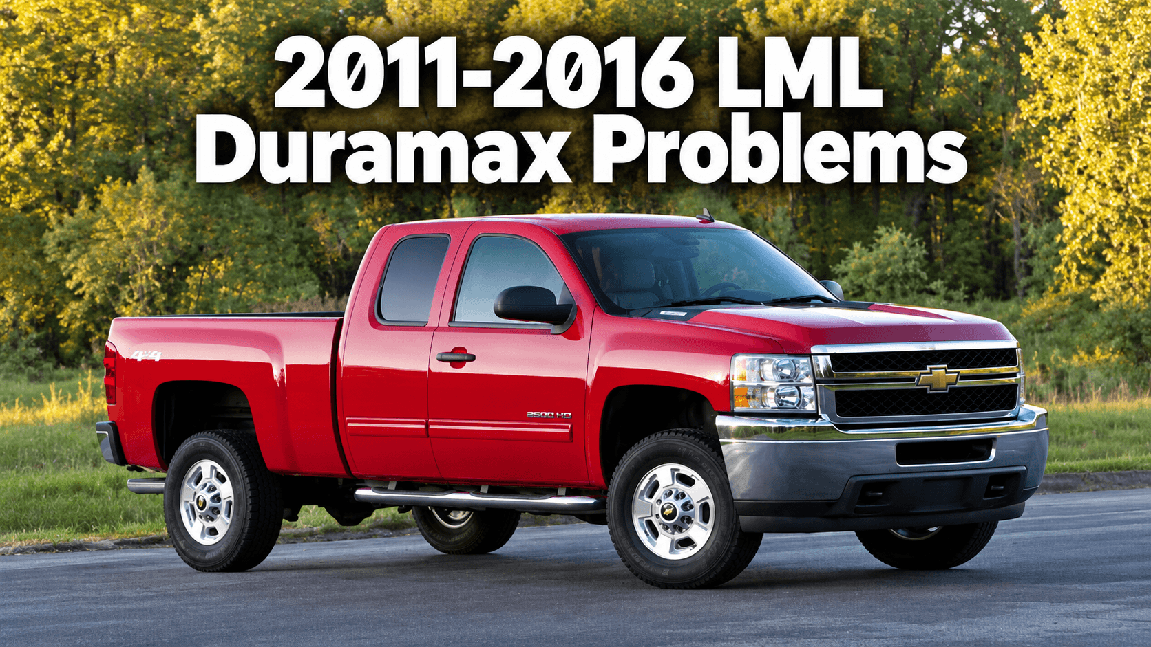
The 6.6L LML Duramax is one of the most popular diesel platforms for aftermarket upgrades. Produced from 2011 through 2016, the LML generation introduced advanced emissions systems including diesel particulate filters (DPF), diesel exhaust fluid (DEF), selective catalytic reduction (SCR), and exhaust gas recirculation (EGR) components.
Installing an LML Duramax delete kit requires careful preparation, correct tuning, proper year-specific fitment, and an organized installation process. This guide covers the complete workflow including tuning preparation, factory emissions component removal, EGR system removal, passenger-side Up-pipe replacement, coolant rerouting, and exhaust installation.
This installation guide is based on a 2011-2016 Chevrolet Silverado HD / GMC Sierra HD equipped with the 6.6L LML Duramax engine. Exact procedures may vary depending on production date, exhaust connection style, cab configuration, previous modifications, and selected tuning package.
Before purchasing components, verify your truck configuration and select the correct diesel delete kit for your application.
Important Emissions Compliance Notice
Before installing any emissions-related aftermarket components, verify the laws and regulations that apply to your vehicle location. Removing or disabling factory emissions equipment may not be legal for vehicles operated on public roads in many regions.
This guide is provided for technical education and installation reference only. Always confirm local requirements before modifying a vehicle.
Additional information:
Choosing the Correct LML Duramax Delete Kit
LML Duramax trucks were produced over several model years, and exhaust connections changed during production. Some trucks use an earlier V-band style connection, while later trucks may use a bolted flange design.
The correct kit depends on:
- Truck model year
- Production date
- Exhaust connection style
- Cab and bed configuration
- Selected tuning platform
- Replacement exhaust configuration
For platform-specific options, view the available Duramax delete kit solutions.
2011-2015.5 LML Duramax Delete Kit Option
Earlier LML trucks are commonly paired with complete kits that combine emissions components, exhaust hardware, and tuning solutions.
One available configuration is the 2011-2015.5 LML Duramax delete kit with V2 tuner .

Before installation, confirm that the included tuner and hardware match the exact truck configuration.
2015.5-2016 LML Duramax Delete Kit Option
Later LML trucks may require different exhaust components and connection styles.
For these applications, review the 2015.5-2016 LML race pipe and EGR delete kit .
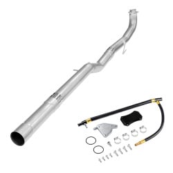
Never select a kit based only on model year. Always verify the physical connection on the vehicle before ordering.
Complete the Tuning Before Removing Hardware
The truck should be successfully programmed before removing factory emissions components. Removing hardware before completing the correct calibration can create compatibility issues with the installed components.
The LML Duramax platform commonly uses two tuning approaches: Mini Maxx V2 or EZ Lynk-based tuning solutions.
EZ Lynk Tuning Option
EZ Lynk provides a connected tuning platform that allows users to manage vehicle calibrations through a compatible device.
For EZ Lynk installations, verify:
- Correct vehicle profile
- Compatible hardware
- Correct calibration file
- Stable battery voltage during programming
Available EZ Lynk products:
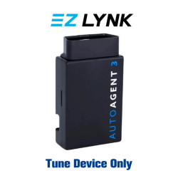
EZ Lynk installation reference:
EZ Lynk Auto Agent Installation GuideMini Maxx V2 Tuning Option
Some LML Duramax delete kits are supplied with Mini Maxx V2 tuning solutions. Before beginning installation, verify the tuner is compatible with the truck and that the correct calibration has been successfully installed.
- Confirm tuner compatibility
- Verify the correct calibration file
- Complete programming before removing hardware
- Maintain stable battery voltage during programming
Mini Maxx V2 resources:
Tools Required for LML Duramax Delete Kit Installation
Prepare all tools before starting the installation. Proper tools reduce the chance of damaged fasteners and make difficult areas easier to access.
- Vehicle lift or heavy-duty ramps
- Floor jack and jack stands
- Wheel chocks
- 10mm socket
- 11mm socket
- 13mm socket
- 13mm ratcheting wrench
- Long 1/2-inch ratchet
- Extensions and universal joints
- Penetrating lubricant
- Exhaust hanger lubricant
- Exhaust hanger pliers
- Flat-head screwdriver
- Pry bar
- Reciprocating saw
- Drain pan
- Coolant-safe lubricant
- Anti-seize compound
- Zip ties
- Heat shielding material
Disconnect the Three Required Engine Connectors
Before removing emissions components, three electrical connectors must be disconnected regardless of whether the complete EGR system is removed.
The required connectors are:
- Front EGR valve connector
- Throttle valve connector
- Rear EGR valve connector
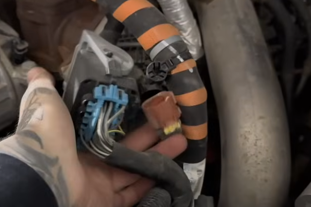
Disconnect the Front EGR Valve Connector
- Locate the front EGR valve connector.
- Release the secondary locking tab.
- Press the connector release.
- Pull the connector housing outward.
- Do not pull on the wiring.
- Protect the connector after removal.
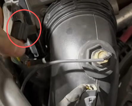
Disconnect the Throttle Valve Connector
- Locate the throttle valve connector.
- Release the locking mechanism.
- Disconnect the electrical plug.
- Secure the harness away from hot components.
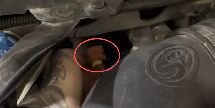
Disconnect the Rear EGR Valve Connector
- Locate the rear EGR valve connector.
- Release the secondary lock.
- Press the main release tab.
- Remove the connector carefully.
- Secure the wiring away from heat and moving parts.
Removing the Factory Exhaust System
After the required electrical connectors are disconnected, the next step is removing the factory exhaust and aftertreatment components. Work from the rear of the truck toward the front and verify every sensor, hose, bracket, and wiring connection has been released before lowering any exhaust components.
Apply Penetrating Lubricant Before Removing Fasteners
Before loosening exhaust hardware, apply penetrating lubricant to all exposed threads. Rusted exhaust fasteners can break easily, especially on trucks exposed to road salt, moisture, or high mileage conditions.
The front exhaust connection style depends on the truck configuration:
- Later LML trucks may use a bolted flange connection.
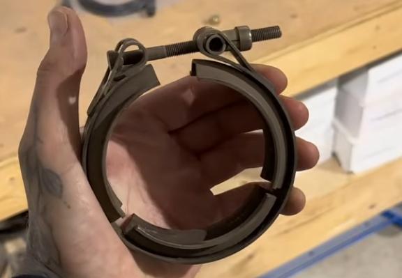
- Earlier LML trucks may use a V-band clamp connection.
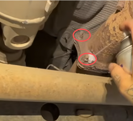
Identify the Factory Exhaust Connection
Inspect the front connection before removing the exhaust assembly. Do not assume the truck uses the same connection style as another LML Duramax.
Bolted Flange Configuration
For trucks equipped with a bolted flange:
- Clean loose rust from exposed threads.
- Apply penetrating lubricant to each fastener.
- Allow time for the lubricant to soak.
- Loosen each fastener gradually.
- Support the exhaust before removing the final fastener.
V-Band Clamp Configuration
Some earlier LML Duramax trucks use a V-band clamp connection.
Before removal:
- Locate the clamp bolt.
- Apply penetrating lubricant to the clamp threads.
- Allow the lubricant to penetrate.
- Loosen the clamp carefully.
- Save the clamp for reuse if it remains in good condition.
Disconnect Factory Exhaust Sensors and Wiring
The factory DPF/SCR assembly contains multiple electrical connectors, sensors, hoses, and support points. Every connection must be released before removing the exhaust assembly.
Disconnect Rear Exhaust Connections First
- Start at the rear of the truck.
- Locate the rear exhaust sensor connector.
- Release the connector lock.
- Disconnect the electrical plug.
- Locate the attached small hoses.
- Remove the hoses carefully.
- Mark hose locations if needed for reference.
Disconnect Frame-Mounted Wiring
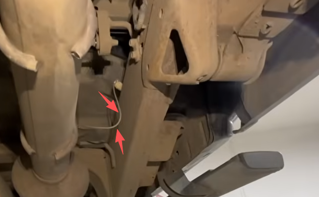
Continue moving forward along the frame rail.
- Locate the wiring connector mounted on the frame.
- Release the locking tab.
- Disconnect the connector.
- Locate the sensor mounted outside the frame rail.
- Disconnect the sensor plug.
- Remove any attached wiring module from the frame if required.
Disconnect the DEF Injector and Related Sensors
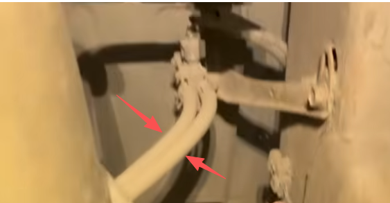
The DEF injector is mounted on the factory aftertreatment assembly.
- Locate the DEF injector connector.
- Disconnect the electrical plug.
- Press both sides of the DEF quick-connect fitting.
- Remove the DEF line.
- Protect the open DEF line from contamination.
- Disconnect nearby sensors around the injector area.
Release All Remaining Exhaust Wiring
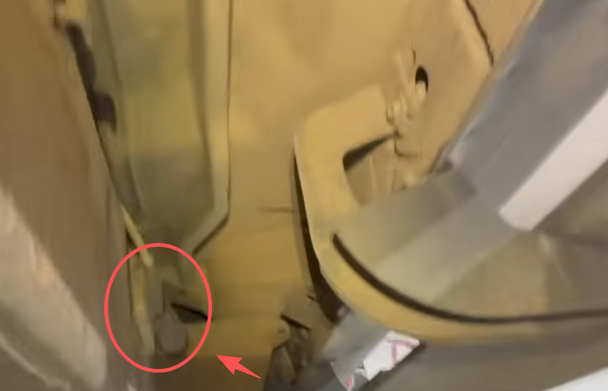
Before moving the exhaust, perform a complete inspection from front to rear.
- Confirm all sensor plugs are disconnected.
- Confirm all pressure hoses are removed.
- Confirm all DEF lines are disconnected.
- Confirm all wiring retainers are released.
- Confirm no harness is attached to the frame or exhaust bracket.
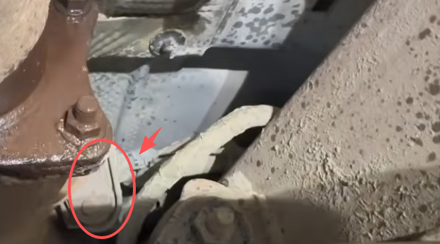
Remove the Factory Exhaust Assembly
Support the Exhaust Before Removal
The factory emissions assembly is heavy and should be supported before removing the final connections.
- Place a transmission jack or wide support under the assembly.
- Support the weight evenly.
- Confirm no sensors or hoses remain connected.
- Remove the remaining support brackets.
Remove Exhaust Hangers
Lubricating exhaust hangers makes removal significantly easier.
- Apply rubber-safe exhaust hanger lubricant.
- Work the rubber isolator around the hanger pin.
- Use exhaust hanger pliers if available.
- Remove each hanger carefully.
- Do not tear reusable rubber isolators.
Remove the Remaining Factory Exhaust Section
Depending on available space, the factory exhaust may be removed as one large section or cut into smaller sections.
If cutting the exhaust:
- Support both sides of the cut.
- Verify no wiring or fuel lines are nearby.
- Avoid cutting near bends or hanger mounts.
- Use proper eye protection.
Remove the Factory DEF Components (Optional)
The DEF tank can be removed depending on the selected configuration.
Disconnect the DEF Tank Harness
- Locate the main DEF tank harness connector.
- Release the locking mechanism.
- Disconnect the connector.
- Remove wiring retainers.
Remove the DEF Tank Shield
- Remove the plastic DEF tank cover bolts.
- Lower the shield.
- Set the hardware aside.
Remove DEF Tank Mounting Straps
- Support the DEF tank.
- Remove the strap bolts.
- Lower the retaining straps.
- Confirm the tank is fully supported.
Disconnect DEF Lines
Whenever possible, disconnect DEF lines using factory fittings instead of cutting them.
- Inspect the DEF lines and connectors.
- Release quick-connect fittings where applicable.
- Cap open lines.
- Lower the DEF tank carefully.
- Remove remaining brackets if required.
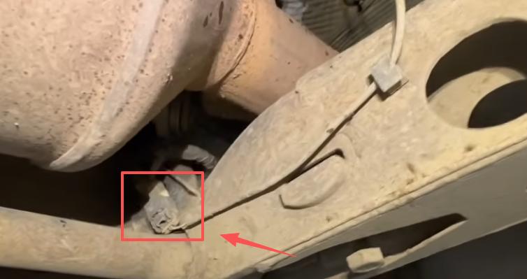
Prepare Passenger-Side Access for EGR and Up-Pipe Work
After the factory exhaust components are removed, additional access is required to reach the passenger-side EGR system and Up-pipe. Removing the passenger-side wheel and inner fender creates additional working space.
Remove the Passenger-Side Front Wheel
- Secure the truck on a stable lifting surface.
- Remove the passenger-side front wheel.
- Store the lug nuts in a clean location.
- Keep the wheel installation hardware organized for reassembly.
Remove the Passenger-Side Inner Fender
- Remove the plastic retainers and screws holding the inner fender.
- Pull the liner away from the wheel opening.
- If the lower section remains attached by factory rivets, it can remain attached.
- Move the liner upward and secure it out of the way.
If the truck is only receiving EGR block-off components and the factory Up-pipe remains installed, inner fender removal may not always be required. However, replacing the Up-pipe requires additional access.
Remove the DEF Fill Neck
Removing the DEF fill neck provides additional room around the passenger-side engine bay area.
- Remove the intake ducting for access.
- Disconnect any sensors attached to the intake system.
- Remove the DEF fill neck mounting hardware.
- Release the fill neck from its mounting location.
- Pull the DEF fill neck out of the engine compartment.
- Store all removed hardware for reinstallation if needed.
Raise the Passenger Side of the Cab for Additional Clearance
The source installation raises the passenger side of the cab slightly to create additional room around the EGR cooler and Up-pipe area. Only a small amount of movement is required.
Loosen the Cab Mounts
- Locate the four passenger-side cab mounts.
- Remove the passenger-side cab mount bolts.
- Move to the driver side of the truck.
- Loosen all four driver-side cab mount bolts.
- Do not remove the driver-side bolts.
Before lifting the cab, inspect all nearby components including:
- Brake lines
- Electrical harnesses
- Ground cables
- Air conditioning lines
- Coolant hoses
- Steering components
Lift the Cab Carefully
- Place a jack under a reinforced pinch weld area.
- Use a wide wood or rubber pad between the jack and cab.
- Raise the cab slowly.
- Check all lines while lifting.
- Lift only enough to create working clearance.
- Install a solid support block between the cab and mount area.
- Remove the jack pressure.
Never work under a cab supported only by a hydraulic jack. The cab must be mechanically supported before working underneath.
Drain the Engine Coolant
The coolant system must be drained before removing the EGR cooler and changing coolant routing.
- Allow the engine to cool completely.
- Place a drain pan below the coolant connection.
- Locate the metal retaining clip.
- Use a pick tool to release the clip.
- Pull the coolant connection apart slightly.
- Allow coolant to drain.
- Once drained, reinstall the connection.
- Lock the retaining clip back into position.
- Verify the connection is secure.
Remove Intake Components for EGR Access
Additional intake components must be removed to access the EGR system and Up-pipe area.
Disconnect Both Battery Negative Terminals
- Turn the ignition off.
- Disconnect the negative terminal from the first battery.
- Disconnect the negative terminal from the second battery.
- Secure the cables away from the battery posts.
Remove the Turbo Silencer
- Locate the turbo silencer housing.
- Remove the two mounting bolts.
- Lift the turbo silencer away.
- Store the bolts with the component.
Remove the Aluminum Intake Pipe
- Disconnect all electrical connectors attached to the intake pipe.
- Remove connected hoses.
- Release the locking ring.
- Rotate the ring counterclockwise.
- Remove the side mounting bolts.
- Remove the lower bracket fasteners.
- Release plastic wiring retainers.
- Remove the aluminum intake pipe.
Remove the Black Plastic Turbo Inlet
- Disconnect rear sensors.
- Loosen the turbo inlet V-band clamp.
- Remove the attached hose clamp.
- Remove the plastic turbo inlet assembly.
- Cover the turbo opening to prevent contamination.
Remove Remaining Intake Piping
- Inspect nearby brackets that may interfere.
- Loosen support brackets if necessary.
- Remove the remaining intake pipe.
- Protect all open intake ports.
Remove Turbo Heat Shield
- Remove the heat shield mounting bolts.
- Lift the shield out of the engine bay.
- Store the shield for reinstallation.
Remove the Factory EGR System
The EGR system consists of the EGR valve, EGR cooler, coolant hoses, and related mounting hardware. Remove each component carefully and keep track of all original fasteners.
Remove the EGR Valve
- Locate the EGR valve assembly.
- Remove the four mounting bolts.
- Support the valve during removal.
- Remove the factory gasket.
- Protect the intake opening from debris.
For additional EGR system information, see:
Disconnect the EGR Cooler
- Remove the EGR cooler mounting hardware.
- Disconnect the coolant hoses.
- Disconnect the remaining brackets.
- Remove the cooler from the engine bay.
Whenever possible, disconnect coolant hoses without cutting them. Preserving factory hose lengths makes coolant rerouting easier during reassembly.
Remove the Factory Up-Pipe
The factory Up-pipe connects the exhaust manifold area to the turbocharger side of the exhaust system. The replacement Up-pipe removes the original EGR branch design.
Remove the Coolant Pipe Blocking Up-Pipe Access
- Locate the metal coolant pipe near the Up-pipe.
- Remove the retaining bolt.
- Move the pipe carefully.
- Release the pipe from the O-ring connection.
- Inspect the O-ring before reuse.
Remove the Six Up-Pipe Bolts
The Up-pipe uses three bolts on each end.
- Apply penetrating lubricant to the bolts.
- Allow time for the lubricant to work.
- Loosen each bolt gradually.
- Alternate between both ends.
- Support the Up-pipe before removing the final bolt.
- Remove the factory Up-pipe.
- Remove old gaskets.
Handling Stubborn Up-Pipe Bolts
If a bolt becomes tight while removing:
- Stop forcing the bolt.
- Thread it back inward slightly.
- Apply penetrating lubricant.
- Work the bolt back and forth.
- Repeat until it releases.
Breaking an Up-pipe bolt can create major repair work, especially if the bolt breaks near the turbocharger or exhaust manifold.
Install the Replacement Up-Pipe
Prepare the New Gaskets
- Install the new gaskets in the correct orientation.
- Confirm the locating features match the flange design.
- Keep sealing surfaces clean.
Apply Anti-Seize to New Hardware
- Clean the new bolts.
- Apply a thin layer of high-temperature anti-seize.
- Avoid applying compound to gasket surfaces.
Transfer the Factory Bracket
- Remove the required bracket from the factory Up-pipe.
- Clean the bracket mounting surface.
- Modify clearance if required.
- Install the bracket onto the replacement Up-pipe.
Install the New Up-Pipe
- Position the new Up-pipe.
- Install both gaskets.
- Start all bolts by hand.
- Confirm proper alignment.
- Tighten both ends gradually.
- Install the transferred bracket.
- Verify the pipe is not under stress.
Always follow the torque specifications provided with the specific Up-pipe hardware. Do not apply torque values from unrelated applications.
Reroute the Coolant System After EGR Cooler Removal
After removing the factory EGR cooler, the original coolant routing must be modified. The goal is to maintain proper coolant circulation while removing the factory EGR cooler from the system.
The main coolant connections involved include:
- Firewall heater hose connection
- Coolant hose behind the turbo area
- Small coolant line near the engine front
- Original EGR cooler coolant connections
Prepare the Replacement Coolant Hose Assembly
- Compare the supplied coolant hose with the factory routing.
- Identify each connection point before cutting any hose.
- Do not remove more material than necessary.
- Confirm the hose length allows smooth routing without kinks.
Connect the Rear Coolant Hoses
- Locate the factory hoses previously connected to the EGR cooler.
- Route the replacement hose assembly between the required connection points.
- Push each hose fully over the fitting.
- Install hose clamps behind the fitting bead.
- Verify the hoses are not twisted.
Connect the Small Coolant Line
- Locate the smaller coolant branch line.
- Connect the small replacement hose.
- Secure the connection with the correct clamp.
- Verify the hose cannot slide off the fitting.
Connect the Front Coolant Line
- Route the remaining hose toward the front of the engine.
- Connect it to the original coolant connection.
- Secure the clamp.
- Check clearance around belts and moving components.
Final Coolant Hose Routing Check
Before continuing, verify:
- No hose is kinked.
- No hose touches the Up-pipe.
- No hose contacts the turbocharger.
- No hose rubs against wiring or brackets.
- Engine movement will not pull the hoses tight.
Install Heat Protection
- Reuse factory heat shields where possible.
- Add heat protection near exhaust components.
- Secure insulation away from moving parts.
- Do not allow hoses to contact hot exhaust surfaces.
Reinstall the Intake System
After the Up-pipe and coolant routing are complete, reinstall the intake components removed earlier.
Install the Turbo Heat Shield
- Position the factory heat shield.
- Install the mounting bolts.
- Confirm the shield does not contact the replacement Up-pipe.
Reconnect the PCV Hose
- Inspect the PCV hose condition.
- Remove the original crimp sleeve if required.
- Install a suitable replacement hose clamp.
- Secure the hose connection.
Install the Turbo Inlet
- Inspect the O-ring condition.
- Clean the sealing surface.
- Install the turbo inlet assembly.
- Reconnect the hose connections.
- Tighten the V-band clamp.
Install the Aluminum Intake Pipe
- Position the intake pipe into place.
- Reconnect the mounting brackets.
- Reconnect active sensors.
- Reconnect power connections.
- Install all original retainers.
Secure Unused Electrical Connectors
Any unused emissions-related connectors should be protected from moisture and secured away from heat.
- Install connector caps where supplied.
- Secure unused connectors with zip ties.
- Keep wiring away from the turbocharger.
- Prevent contact with exhaust components.
- Do not leave wiring hanging near moving parts.
Lower the Cab and Complete Engine Bay Assembly
Lower the Cab Carefully
- Inspect all hoses and wiring before lowering.
- Confirm no tools remain under the cab.
- Raise the cab slightly.
- Remove the support block.
- Lower the cab slowly.
- Check for pinched hoses or wiring.
- Allow the cab to fully settle onto the mounts.
Reinstall Cab Mount Hardware
- Install all passenger-side cab mount bolts.
- Install all previously loosened driver-side bolts.
- Start all bolts by hand.
- Confirm proper thread engagement.
- Tighten according to factory specifications.
Never operate the vehicle with missing or loose cab mount hardware.
Reconnect Batteries
- Confirm all electrical work is complete.
- Reconnect both negative battery terminals.
- Tighten battery connections.
Refill Coolant and Perform Initial Testing
Refill the Cooling System
- Confirm all coolant connections are locked.
- Check every hose clamp.
- Add the correct coolant type.
- Fill slowly to the correct level.
- Do not reinstall the inner fender until leak checks are complete.
First Engine Start
- Start the engine.
- Allow it to idle.
- Monitor coolant connections.
- Check for leaks.
- Listen for abnormal exhaust sounds.
- Check for warning lights.
After reaching operating temperature, allow the truck to cool completely and recheck coolant level. Additional coolant may be required after air leaves the system.
Install the Replacement Exhaust System
The final exhaust installation depends on whether the truck uses replacement pipes or a complete exhaust system.
Option 1: Install DPF Replacement Pipes
When retaining the factory tailpipe, measure carefully before cutting any factory tubing.
Measure Before Cutting
- Compare the replacement pipe with the factory exhaust.
- Determine required overlap length.
- Identify the correct straight section for cutting.
- Mark the cutting location.
- Measure again before cutting.
Cut the Factory Straight Pipe
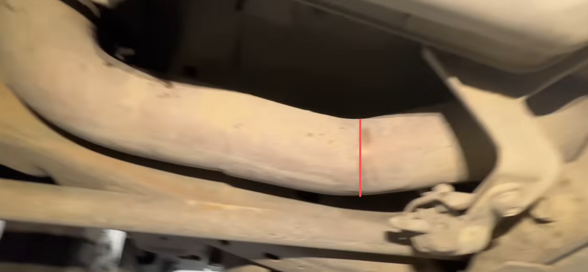
- Support the exhaust on both sides of the cut.
- Verify no wiring or fuel lines are nearby.
- Cut the marked straight section.
- Deburr the pipe edge.
- Clean all metal debris.
Install Replacement Pipe
- Install the exhaust clamp over the pipe.
- Slide the replacement pipe into position.
- Confirm proper overlap.
- Align the exhaust system.
- Tighten the clamp after final positioning.
Option 2: Install Full 5-Inch Exhaust System
Install Front Exhaust Section
- Position the front exhaust pipe.
- Reconnect the factory support bracket.
- Install the front connection hardware loosely.
- Allow movement for final alignment.
Install Intermediate Exhaust Sections
- Install the transition pipe.
- Install exhaust clamps loosely.
- Connect rubber hangers.
- Continue installing rear sections.
Install Over-Axle Pipe
- Position the over-axle section.
- Clear the rear axle and suspension components.
- Connect the hanger points.
- Keep clamps loose during adjustment.
Install Tailpipe
- Install the final tailpipe section.
- Align the exhaust tip.
- Confirm body clearance.
- Confirm spare tire clearance.
Final Exhaust Alignment
Before tightening all clamps, verify:
- No contact with the frame.
- No contact with suspension components.
- No contact with brake lines.
- No contact with wiring.
- Proper exhaust hanger alignment.
- Correct tailpipe position.
Tighten Exhaust Connections
Tighten the exhaust system from the front toward the rear.
- Front connection.
- Support bracket.
- Intermediate clamps.
- Rear exhaust clamps.
- Tailpipe clamp.
Final Inspection Checklist
Electrical
- All required connectors disconnected.
- Unused connectors protected.
- Harnesses secured away from heat.
- Battery connections tightened.
Cooling System
- All coolant hoses secure.
- No coolant leaks.
- Correct coolant level.
- Heat protection installed.
Up-Pipe and EGR System
- New Up-pipe installed correctly.
- New gaskets installed.
- Fasteners tightened properly.
- EGR block-off plate installed.
Exhaust
- All clamps tightened.
- No exhaust leaks.
- No rattles.
- No contact with chassis components.
- Exhaust hangers aligned.
Installation Guides & Technical Manuals
For additional installation details, hardware specifications, and product-specific instructions, refer to the official technical manuals below.
- SuncentAuto Installation Guides Library
Browse installation instructions and technical documentation for diesel performance products and vehicle-specific upgrades.
- 2011-2016 6.6L Duramax LML Race Pipe Installation Manual (PDF)
Detailed installation reference for LML Duramax race pipe systems, including exhaust component installation procedures and hardware information.
- 2011-2016 6.6L Duramax LML EGR Delete Kit Installation Manual (PDF)
Installation instructions covering EGR delete components, coolant routing, and related hardware installation procedures.
- Mini Maxx V2 Installation Guide (PDF)
Reference guide for Mini Maxx V2 tuner installation and setup procedures.
- EZ Lynk Auto Agent 3 Installation Guide (PDF)
Installation reference for EZ Lynk Auto Agent 3 device setup and configuration.